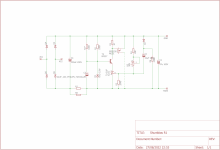
I fixed another error in the 1.5A regulators.
This one works, well, R3 is on the way, but that is a commercial endeavour.
Hello v4lve lover.
Won't you have a lot of trouble adding a rectifier bridge to your PCB design from # 100? Then the project was full.
Thank you.
Piotr
Won't you have a lot of trouble adding a rectifier bridge to your PCB design from # 100? Then the project was full.
Thank you.
Piotr
Hi Piotr,
There are good reasons why there is no bridge rectifier on that PCB. Those create noise if they are to close to the sensitive circuits. better to use the board i made for these modules, or any other of the Rectifier plus capacitor boards.
There are good reasons why there is no bridge rectifier on that PCB. Those create noise if they are to close to the sensitive circuits. better to use the board i made for these modules, or any other of the Rectifier plus capacitor boards.
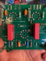
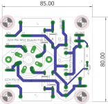
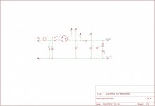
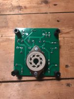
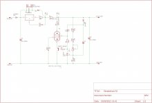
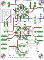
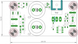
GZ34 5AR4 PCB
I made this little 80x85mm PCB for using tube rectification with transformers with or without a centertap. For AC voltages up to about 275VAC. 450VDC being limited by the 450V 47uF caps.
I have these boards available currently including all the parts. And can make packages. Where you get all the parts, a BOM and a short builders guide.
Cheers, V4lve.
Attachments
Last edited:
Very nice and useful PCB, thanks.
I like the possibility of having a CRC or CLC.
To be on the safer side I will replace C3 with a bleeding resistor.
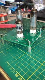
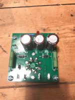
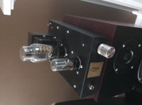
I’m using your other PCBs, very useful. Below is the HV Pcb for my OTL 6AS7 Headphone amp, it’s a CLCLC and quiet as a mouse.
Thanks
Eric
I like the possibility of having a CRC or CLC.
To be on the safer side I will replace C3 with a bleeding resistor.
I’m using your other PCBs, very useful. Below is the HV Pcb for my OTL 6AS7 Headphone amp, it’s a CLCLC and quiet as a mouse.
Thanks
Eric
Attachments
To be on the safer side I will replace C3 with a bleeding resistor.
There is R4+LED as bleeder.

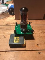
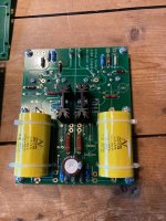
12B4 Linestage. not free this time
Im doing a batch of 12B4 linestage PCB's as bare boards or parts kits.
These will be marked up, to help me pay some of my bills, cause allthrough my paypal is on some of the boards, i haven't received the spontaneous donations i was hoping for.
Please inquire Via PM.
Im doing a batch of 12B4 linestage PCB's as bare boards or parts kits.
These will be marked up, to help me pay some of my bills, cause allthrough my paypal is on some of the boards, i haven't received the spontaneous donations i was hoping for.
Please inquire Via PM.
Attachments

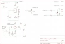
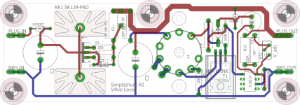
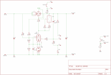
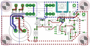
Simpleshunt R1
EL84 EL86 PL84 based shunt regulator.
D1 serves to lower the G2 voltage for use with EL86/PL84 D2 is protection for the ref gate of the TL431.
C2 needs to be low leakage electrolytic or a 1uF 400VDC film cap.
Is made for under top-plate mounting so the socket is on the rear.side
EL84 EL86 PL84 based shunt regulator.
D1 serves to lower the G2 voltage for use with EL86/PL84 D2 is protection for the ref gate of the TL431.
C2 needs to be low leakage electrolytic or a 1uF 400VDC film cap.
Is made for under top-plate mounting so the socket is on the rear.side
Attachments
This Thread needs another tube regulator, Ive updated the 6C19P regulator board with a 10M45S. This makes for a nice regulator to feed Phono stages.
Order at will, also available from yours truely in a week or so.

Mod Edit. Attached Gerber files removed as requested.
Order at will, also available from yours truely in a week or so.
Mod Edit. Attached Gerber files removed as requested.
Attachments
Last edited by a moderator:
Curious to see how much extra performance that 10M45 can squeeze out compared to the original board I have
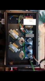
I made another board, this time for a bias regulator based on the Pmillet shunt bias supply.
Original can be found here: http://www.pmillett.com/bias_supply.html
This is a mono version for SE monoblocks. Dimensions 50x100mm
I used some hard to source parts, like the BF337 because i have quite a few of those transistors. Also the tantalum cap over the zener diode is sub-standard.
I will be ordering some more boards for this project soon, PM if interested.
Attachments
Last edited:
This is a board for an extremely compact maida style regulator. In short the EXCmaida R1
Board dimensions are again 50x100mm. Cooler is a SK129-38 or SK129-50.
Can be used with Full wave or Bridge rectification.
Board dimensions are again 50x100mm. Cooler is a SK129-38 or SK129-50.
Can be used with Full wave or Bridge rectification.
Attachments
-
EXC maida R1 gerbers.zip95.5 KB · Views: 163
-
 photo_2022-09-06_13-02-30.jpg97 KB · Views: 347
 -
 photo_2022-09-06_13-02-20.jpg160 KB · Views: 355
 -
 photo_2022-09-06_13-02-10.jpg137.4 KB · Views: 436
 -
 Schematic.png370.2 KB · Views: 447
 -
 Board image.png53.4 KB · Views: 426
 -
 Board image dimensions.png55.5 KB · Views: 314
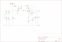
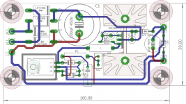
This is a giant of a board, it measures 50x100mm and can be used to build a 5A capable 10V power supply for 211/845/813 tubes. I think this board can be modified to give 20VDC from a 18VAC supply as well for GM70
It uses one of these "Saligny" active rectifier PCB's available here: https://www.diyaudio.com/community/threads/ideal-bridge-rectifier-gb.333844/
The controller is a MIC5156yn. Axillary components include a DB102 bridge rectifier and 78L09 in TO92 for the gate drive supply.
Suggested FET is a IXTH75n80L2 or equivalent L2 series mosfet. I have a large stock of Harris branded IRFP254 that have good SOA due to being a very old part with production dates in the mid 90's that i use for this board.
Specs:
Output current :5A (Limited by the ripple current of the two 25mm snap-in capacitors) I use these caps on the 10V version: Mouser stock: 871-B41231B4229M00
output voltage : 5-12.5V adjustable. Adjust feedback resistors for higher values. Reference voltage on the MIC5156 is 1.25V so its quite easy to calculate a new divider/Pot value.
Input voltage minimum: 9VAC or the LT4320 stops functioning correctly
Input voltage maximum: 20VAC. Will need 63V rated C5 C6 in that case.
Noise plus hum: Less than 1mV in the prototype.
Short circuit protection: No
Dropout voltage: Approx 0.5V maximum at 5A
Additional information: The 78L09 is needed to down-regulate the gate driver supply for the IC because the IC internally clamps the gate driver supply to 12V with a Zener diode.
I will be ordering boards for this project, please PM if interested.
Attachments
-
Gerbers Compact Mic5156 regulator R1.zip101.6 KB · Views: 114
-
MIC5156 compact regulator.sch765.2 KB · Views: 114
-
MIC5156 compact regulator.brd82.3 KB · Views: 102
-
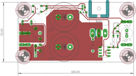 MIC5156 compact regulator board image top layer.png14.2 KB · Views: 269
 -
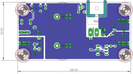 MIC5156 compact regulator board image bottom layer.png14.2 KB · Views: 192
 -
 MIC5156 compact regulator board image no copper.png11.8 KB · Views: 277
 -
 Schematic.png11.9 KB · Views: 255
- Home
- Amplifiers
- Tubes / Valves
- V4lve lover's free Gerbers thread