During the course of the past 10 years I have been prototyping some 40 tube based audio projects.
All kinds, SE, PP, PPP, Circlotron, Current Dumping, SE Spud, PP Spud, Phono, OTL, SMPS, conventional PS, Hybrid etc.
None is a straight copy of a published design but different tubes, redesigned circuits, cheap OPT a.s.o. but all work well within their limits.
Lately I ran out of ideas for audio, so during the last 6 months I tried something different, non audio:
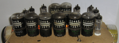
A 24 Hour Digital Clock with just 16 Vacuum Tubes which could have been built in the 1950's.
Background:
To my knowledge no all tube clocks were built in the 50's or 60's.
Only four attempts to build such a clock in modern times are known:
Nr. 1 is a project which took an individual enthusiast 10 years to complete, 97 vacuum tubes plus 6 nixies:
http://www.jogis-roehrenbude.de/Leserbriefe/Bruegmann-Digital-Roehren-Clock/Digital-Roehrenuhr.htm
Nr. 2 was a cooperative semester project at Technical University of Berlin, sponsored by a company and on display at a sales show, 70 tubes plus 6 nixies:
https://www.emsp.tu-berlin.de/menue...nik_back_to_the_roots/die_digitaluhr_oncilla/https://www.emsp.tu-berlin.de/fileadmin/fg232/Lehre/MixedSignal/Dateien/Back2TheRoots/02_ONCILLA.pdf
Nr. 3 is based on a set of vintage Beckman counter modules, modified for nixie display, 30 vacuum tubes plus 6 nixies;
https://linearlook.com/eldocountry/projects/tubeclock.html
Nr. 4 is similar but predates Nr.3, 30 vacuum tubes, display has 10 indicator lamps per decade:
https://www.selectric.org/tubeclock/
There are clocks out which use decade counter tubes for display but all the difficult tasks are done by a microcontroller like in this one:
http://www.tube-tester.com/sites/nixie/different/e1t-clock/e1t-clock.schem.pdf
All four serious vacuum tube based clocks use flip-flops for counting.
And because it takes 4 dual triodes per hexadecimal digit plus a couple more to do the reset trick at 10, 6 and 24, this is where most of the vacuum is spent.
My thinking was that if I could avoid flip-flops and the associated logic altogether it should be possible to get away with a lot less.
Now, the Philips E1T Beam Deflection Counter Tube, does the decimal counting all by itself, displays the result, resets itself with the 10th pulse, provides a carry signal fto trigger the next stage, acts as a storage device and even allows readout of the stored number, albeit in form of an analogue voltage on pin a2 proportional to the displayed number. This works backwards, too, and can be used to preset.
https://www.radiomuseum.org/tubes/tube_e1t.html
Unfortunately the official application documents for the E1T require one E90CC pulse shaper per decade for 30 kHz operation and two E92CC per decade for 100kHz.
http://www.tube-tester.com/sites/nixie/dat_arch/E1T_Philips_Book_1954.pdf
All kinds, SE, PP, PPP, Circlotron, Current Dumping, SE Spud, PP Spud, Phono, OTL, SMPS, conventional PS, Hybrid etc.
None is a straight copy of a published design but different tubes, redesigned circuits, cheap OPT a.s.o. but all work well within their limits.
Lately I ran out of ideas for audio, so during the last 6 months I tried something different, non audio:
A 24 Hour Digital Clock with just 16 Vacuum Tubes which could have been built in the 1950's.
Background:
To my knowledge no all tube clocks were built in the 50's or 60's.
Only four attempts to build such a clock in modern times are known:
Nr. 1 is a project which took an individual enthusiast 10 years to complete, 97 vacuum tubes plus 6 nixies:
http://www.jogis-roehrenbude.de/Leserbriefe/Bruegmann-Digital-Roehren-Clock/Digital-Roehrenuhr.htm
Nr. 2 was a cooperative semester project at Technical University of Berlin, sponsored by a company and on display at a sales show, 70 tubes plus 6 nixies:
https://www.emsp.tu-berlin.de/menue...nik_back_to_the_roots/die_digitaluhr_oncilla/https://www.emsp.tu-berlin.de/fileadmin/fg232/Lehre/MixedSignal/Dateien/Back2TheRoots/02_ONCILLA.pdf
Nr. 3 is based on a set of vintage Beckman counter modules, modified for nixie display, 30 vacuum tubes plus 6 nixies;
https://linearlook.com/eldocountry/projects/tubeclock.html
Nr. 4 is similar but predates Nr.3, 30 vacuum tubes, display has 10 indicator lamps per decade:
https://www.selectric.org/tubeclock/
There are clocks out which use decade counter tubes for display but all the difficult tasks are done by a microcontroller like in this one:
http://www.tube-tester.com/sites/nixie/different/e1t-clock/e1t-clock.schem.pdf
All four serious vacuum tube based clocks use flip-flops for counting.
And because it takes 4 dual triodes per hexadecimal digit plus a couple more to do the reset trick at 10, 6 and 24, this is where most of the vacuum is spent.
My thinking was that if I could avoid flip-flops and the associated logic altogether it should be possible to get away with a lot less.
Now, the Philips E1T Beam Deflection Counter Tube, does the decimal counting all by itself, displays the result, resets itself with the 10th pulse, provides a carry signal fto trigger the next stage, acts as a storage device and even allows readout of the stored number, albeit in form of an analogue voltage on pin a2 proportional to the displayed number. This works backwards, too, and can be used to preset.
https://www.radiomuseum.org/tubes/tube_e1t.html
Unfortunately the official application documents for the E1T require one E90CC pulse shaper per decade for 30 kHz operation and two E92CC per decade for 100kHz.
http://www.tube-tester.com/sites/nixie/dat_arch/E1T_Philips_Book_1954.pdf
Attachments

Last edited by a moderator:
Realization:
Furtunately we do not need such speeds as the maximum clock frequency will be 100Hz, derived from mains frequency (one hassle less in 50Hz country where I live).
And although Philips never mentioned it in their data sheets it is indeed possible to cascade multiple E1Ts without any auxiliary tubes.
So the E1T opens up the opportunity to do away with those flip-flop graveyards and simplify logic circuitry, I thought.
Unfortunately time keeping never caught up with metrication (or metrification ?) otherwise 8 of those E1T tubes would be all that is needed to run a decimal clock from a 100Hz signal.
Instead we are left with the problem to reset seconds and minutes from 59 to 00 and hours from 23 to 00.
My solution to the 60's problem is to sense the before mentioned analogue voltage which drops by around 15V for each step to the next digit and compare it to a reference from a devider (one E90CC) and use its output to trigger a pulse shaper (another E90CC) to reset one E1T and advance the next E1T.
Solving the 24's problem turned out to be painful. The 60's method worked for the "4" but no longer for the "2" as the voltage level for the "2" was too high (~ 220V) for the comparator to work reliably with a B+ of 300V. Another issue was that I had only 3 E90CCs available for the job restricted by heater string arrangement. After many a detour I realised that all I needed to do was to sense said voltage with a cathode follower, and have a string of zeners to discriminate between "0"s or "1"s and "2"s of the tens of hours. "0" and "1" would cause current through the zeners, "2" would not. The zener current could forward bias a diode which in turn would suppress the triggervfrom the "4" of the hours. Because zeners did not exist in the 1950's they are considered heresy and must be replaced by glow discharge tubes of course. At first I tried indicator lamps but they turned ourt to be unreliable andvtheir burn voltages degraded quickly in less than 24 hours of operation. In the end a string of three 75C1 regulator tubes seem to do the job reliably, although I hate those three additional tube sockets. Several 1N4148 siliconvdiodes replace the OA55 germanium types usd by philips in their 1954 paper. Both are specified 100V max.
To build the prototype and do the necessary experiments starting with a pair of E1Ts and gradually extend and test, debug, modify the circuitry only used tubes were used. The E1Ts in my possession are in various states, fromvbrand new in original boxes to well worn ones ranging from low emission to worn fluorescent screen, one even has two times the emission current when compared to the spec sheet ! Strangely enough screen wear and cathode wear don't correlate. Often those with fluorecent layer almost gone have normal cathode currents, whereas those with low emission show no signs of wear on the display area. Anyway, I found that they can all be resucitated by adjustment of the cathode resistor, 15kohm nominal, down to 12 or 10kohm for low emission specimen, and 20kohm for the strange blip.
A very crude method is implemented to set the clock to a specific starting time . A simple on-off-on switch toggles between fast-forward, stop, and normal run. Fast-forward directs the 100Hz signal directly to the 10s of seconds stage, which means a 1000x speed-up. A more luxury method could be implemented by individually pre-setting each E1Ts a2 pin to a voltage from a resistor ladder network with a potential representing the respective number.
Attachments
Last edited by a moderator:
Summary:
A 24 Hour Digital Clock with just 16 Vacuum Tubes which could have been built in the 1950's was prototyped and seems to work satisfactorily.
Tube Lineup:
1 x E90CC - 100Hz generator and pulse shaper
2 x E1T - 100Hz to 1Hz pre-scaler
2 x E1T - seconds counter and display
2 x E90CC - reset seconds from 59 to 00
2 x E1T - minutes counter and display
2 x E90CC - reset minutes from 59 to 00
2 x E1T - hours counter and display
3 x E90CC - reset hours from 23 to 00
3 x 75C1 - 24 hrs detection reference
Power Supply:
230V / 24V mains transformer (4 heater strings, 2 x 6V/0.3A, 2 x 6V/0.4A)
24V / 130V back-to-back transformer (310V/50mA DC through doubler)
55 - 60 W power from mains 230V / 50Hz
Attachment is an animated GIF showing the transition from 16:59h to 17:09
Attachments

Cool!
Ronald Dekker also made a dekatron clock, but he only uses them as displays and does all the counting with semiconductors, https://www.dos4ever.com/decatron/decatronweb.html
I don't know if you ever visited The National Museum of Computing in Bletchley, England, but I can recommend it. They have a computer that uses 828 dekatrons for program and data memory and some more cold and hot cathode valves for arithmetic, see https://www.tnmoc.org/witch
By the way, you only use 8 vacuum tubes, as all the others have a gas filling.
nope, the E1T is a real vacuum beam deflection tube, similar to an oscilloscope CRT it uses electrostatic deflection plates to direct the electron beam to different spots on the fluorescent screen; the ingenious trick is that the beam has 10 stable positions and a short controlled voltage spike to one of the electrodes causes the beam to jump to the next stable position, until it hits a reset plate.
By the way, you only use 8 vacuum tubes, as all the others have a gas filling.
The "Dekatron" is a cold cathode neon gas tube.Cool!
Ronald Dekker also made a dekatron clock, but he only uses them as displays and does all the counting with semiconductors, https://www.dos4ever.com/decatron/decatronweb.html
The E1T which I use is a "Trochotron" vacuum beam deflection type.
They are often confused but fundamentally different.
You're absolutely right, and I was wrong calling it a dekatron. It can also work reliably in the dark without priming then.
Article, 1st page only, 1957: https://www.jstor.org/stable/24941923To my knowledge no all tube clocks were built in the 50's or 60's.
Compiled digest: https://archive.org/details/Project...tific_American/page/531/mode/2up?view=theaterProjects for the Amateur Scientist
Scientific American, 1960

You seem to be trusting your power utility? Today that is good in many places, although it can play catch-up every day. W.W. Withrow in Teague Texas, 1957, discovered what my father in Missouri already knew: at some times and places, the town Head Engineer owned a very fine pocket-watch. Every morning he set it by the railroad clock (synced from DC via telegraph), came to work, compared to an electric clock at the generator, and trimed the engine regulator to reduce the error.
This one differs in using a crystal, and using an electric clock for counting and display. (So yes, a GREAT reduction in complexity.)
NBS (where the US got time) had a much bigger reference clock at the Observatory in Wash DC.
Prior art: https://en.wikipedia.org/wiki/WWV_(radio_station)#/media/File:WWVNBSRadioStation_015.jpg
Last edited:
Well in UK it's kept pretty close to 50Hz and if it goes below 48.8Hz a load of people's days get ruined as the network sheds load. Happens every few years. Currently 50.003Hz
That's over a half-hour a day. The worst wind-up and battery clocks/watches I've ever owned never slipped that much.if it goes below 48.8Hz
5 seconds a day. Good, but not good enough for good navigation, astronomy and other purposes.Currently 50.003Hz
Since many houses used to have a special 'clock point' wired over the mantle in the sitting room, and maybe in the kitchen over the door, I had always been under the impression that the utilities ensured a daily average of 50 Hz so that mains clocks did not have to be adjusted, except during strikes and 3-day weeks.
Well, the output of this clock is to a synchronous motor, an electromechanical display ...Article, 1st page only, 1957: https://www.jstor.org/stable/24941923
Compiled digest: https://archive.org/details/Project...tific_American/page/531/mode/2up?view=theaterProjects for the Amateur Scientist
Scientific American, 1960
You seem to be trusting your power utility? Today that is good in many places, although it can play catch-up every day.
I think I have seen those single tube dividers before;
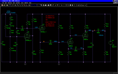
I have come up with something similar recently:
A PCF80 pierce quartz oscillator followed by a single E90CC divide by 10, rather analogue than digital but works quite well;
1MHz quartz down to 100kHz in this example. I think there is a trim pot somewhere, too.
Using a 100kHz quartz and 3 such ./.10 divider stages (each stage 10x cap value) would get me 100Hz to feed the first counter tube in my clock instead of from mains ... just 3 more tubes then ... I am tempted ...
Attachments
Well the 48.8Hz was the point at which a bad thing happened. About 1 million homes were shed from the network due to a power glitch and only occurs every 5-10 years. The licence terms are +/-1% and generally its +/-0.2Hz With variation over a 24 hour period I would suspect it's as accurate as a std quartz watch. Just checking and the average over the last 24 hours was 49.99Hz. Not bad, but of course you can do better if you need accurate time.That's over a half-hour a day. The worst wind-up and battery clocks/watches I've ever owned never slipped that much.
5 seconds a day. Good, but not good enough for good navigation, astronomy and other purposes.
- Home
- Amplifiers
- Tubes / Valves
- A 24 Hour Digital Clock with just 16 Vacuum Tubes