I am stumped 🙁
I've recently resurrected a DIY multi-channel amplifier that I built about 15 years ago, mostly from commercial kit PCBs. It has balanced inputs and was previously used with a DCX2496 (balanced outputs) with no hum, until the DCX2496 died and I later blew up a channel on this amp. Fast forward, the DCX2496 is replaced with a Dayton DSP-408 and the amp is repaired... but it hums with a very slight buzz if there is anything connected to an input.
If no amp inputs are connected, it is quiet - it's not going to win any nV^2/Hz awards, but good enough to have in the loungeroom. As soon as I plug a cable into the inputs, it starts humming. If I touch the end of the cable, obviously lots of noise. Plug the cable into the output of a source (e.g. DSP-408, or the pre-outs of a receiver) and the hum is there - for the channels that are connected.
With some signal playing through it, it sounds fairly good but that hum is audible and very annoying during quiet parts. I suspect it also exists in the mid+tweet channels, which cannot be a good thing even though it's only a couple hundred mV.
The amplifier and its sources are all in the one rack; there are no long cables except the speaker cables. The rack has a PDU and it's all powered from a single powerpoint.
The amp box is a steel 3U rack case, very full, which contains:
The fact that it's quiet with no inputs connected means that I don't think there are any severe ground-topology issues in the power supplies, e.g. there are no rectifier currents within the signal path that cause the classic buzz.
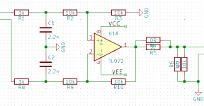
Inputs are/were differential, using a very simple active differential receiver - see attached schematic (which doesn't include decoupling but obviously it's there). I will not pretend that it has fantastic CMRR but it has previously not been a problem, and the cables in use are very short. It's assembled using a PCB of my own, NE5532s and 1% thin-film resistors, all 0805. The balanced-received circuits have a linear regulated supply which is derived from the 36V supply for the chip amps, therefore the ground of the unbalanced outputs is the ground of the chip-amp (+-36V) supply. Because there are 6 differential receivers with unbalanced outputs which all share a single ground, this is the point where the grounds of the two different amplifier-types join up. There is skinny shielded wire from the balanced-receiver SE outputs to the input of each (SE) power amplifier, and these shield/grounds all meet at the differential boards.
The input ports to the box are XLR wired in the usual way. Pins 2 and 3 go to the balanced input circuit, pin 1 I have tried to chassis-ground, power-supply ground, or floating. I have short - too short! - RCA to XLR cables which are used as the inputs. They are mic cable, two-core with a screen. Screen goes to pin 1 at the XLR end, red and white go to pins 2 and 3. At the RCA end, the tip and sleeve go to red and white, i.e. the screen is (was...) discontinuous at the source end.
Chassis ground of both the amplifier and the source (pre-outs on a Yamaha receiver) are connected together through the PDU: Class I safety grounds. The Yamaha has RCA outputs, the screen of which is connected to chassis ground within the Yamaha. The pre-outs go via the DSP-408; the DSP is powered from a floating (Class II) DC wall-wart and it connects the screen/ground of all of its input and output RCA ports together internally as you'd expect.
Things I have tried so far, to no avail:
That's a bit of a wall of text sorry, so I am drawing out all the internal and external wiring now in KiCad.
If anyone can spot my error and say "this is what you've done wrong", great, otherwise I'm looking for suggestions for things I can test in order to try to isolate the problem.
I saw this thread but I am not sure it applies here. The differential inputs should provide sufficient separation between the grounds, or so I thought... There are definitely ground loops inside the case, e.g. via the screens of the unbalanced signals from the balanced inputs, to the amp boards, then back through the PSU via 2 paths, but they do not seem to be causing any problem, noting that it is silent with the inputs floating.
I've recently resurrected a DIY multi-channel amplifier that I built about 15 years ago, mostly from commercial kit PCBs. It has balanced inputs and was previously used with a DCX2496 (balanced outputs) with no hum, until the DCX2496 died and I later blew up a channel on this amp. Fast forward, the DCX2496 is replaced with a Dayton DSP-408 and the amp is repaired... but it hums with a very slight buzz if there is anything connected to an input.
If no amp inputs are connected, it is quiet - it's not going to win any nV^2/Hz awards, but good enough to have in the loungeroom. As soon as I plug a cable into the inputs, it starts humming. If I touch the end of the cable, obviously lots of noise. Plug the cable into the output of a source (e.g. DSP-408, or the pre-outs of a receiver) and the hum is there - for the channels that are connected.
With some signal playing through it, it sounds fairly good but that hum is audible and very annoying during quiet parts. I suspect it also exists in the mid+tweet channels, which cannot be a good thing even though it's only a couple hundred mV.
The amplifier and its sources are all in the one rack; there are no long cables except the speaker cables. The rack has a PDU and it's all powered from a single powerpoint.
The amp box is a steel 3U rack case, very full, which contains:
- 2x300VA+20VA toroids feeding classic bridge rectifier + cap power supplies at +- 36V, 50V and 60V.
- the low voltage supply powers four 50W chip amps (for mids+tweets)
- the high voltage supplies drive a pair of 100W discrete AB amps (for woofers)
- an arduino doing fan-control work plus switching the mains in accordance with a remote-in signal, etc
- outputs go to a pair of three-way speaker boxes via 8-pole speakons and braided fig-8
The fact that it's quiet with no inputs connected means that I don't think there are any severe ground-topology issues in the power supplies, e.g. there are no rectifier currents within the signal path that cause the classic buzz.
Inputs are/were differential, using a very simple active differential receiver - see attached schematic (which doesn't include decoupling but obviously it's there). I will not pretend that it has fantastic CMRR but it has previously not been a problem, and the cables in use are very short. It's assembled using a PCB of my own, NE5532s and 1% thin-film resistors, all 0805. The balanced-received circuits have a linear regulated supply which is derived from the 36V supply for the chip amps, therefore the ground of the unbalanced outputs is the ground of the chip-amp (+-36V) supply. Because there are 6 differential receivers with unbalanced outputs which all share a single ground, this is the point where the grounds of the two different amplifier-types join up. There is skinny shielded wire from the balanced-receiver SE outputs to the input of each (SE) power amplifier, and these shield/grounds all meet at the differential boards.
The input ports to the box are XLR wired in the usual way. Pins 2 and 3 go to the balanced input circuit, pin 1 I have tried to chassis-ground, power-supply ground, or floating. I have short - too short! - RCA to XLR cables which are used as the inputs. They are mic cable, two-core with a screen. Screen goes to pin 1 at the XLR end, red and white go to pins 2 and 3. At the RCA end, the tip and sleeve go to red and white, i.e. the screen is (was...) discontinuous at the source end.
Chassis ground of both the amplifier and the source (pre-outs on a Yamaha receiver) are connected together through the PDU: Class I safety grounds. The Yamaha has RCA outputs, the screen of which is connected to chassis ground within the Yamaha. The pre-outs go via the DSP-408; the DSP is powered from a floating (Class II) DC wall-wart and it connects the screen/ground of all of its input and output RCA ports together internally as you'd expect.
Things I have tried so far, to no avail:
- connecting PSU ground to chassis ground (good), or floating (a bit unsafe)
- with PSU ground floating, connect ground at the differential input board to chassis ground (slightly less unsafe but still not great)
- connecting and disconnecting screen (pin 1) in XLR sockets to chassis ground
- remove the differential input boards, connecting the inputs of each amp board directly to pins 2+3 of the XLR sockets (this connects the grounds of the two power supplies only via the sleeves in the various RCA jacks - quite unsafe, and a risk to the DSP if there were a PSU fault)
- connect and/or disconnect the screen of the cables to the RCA sleeve at the source end, thereby tying the source & amp chassis together through cable-screens, or not
That's a bit of a wall of text sorry, so I am drawing out all the internal and external wiring now in KiCad.
If anyone can spot my error and say "this is what you've done wrong", great, otherwise I'm looking for suggestions for things I can test in order to try to isolate the problem.
I saw this thread but I am not sure it applies here. The differential inputs should provide sufficient separation between the grounds, or so I thought... There are definitely ground loops inside the case, e.g. via the screens of the unbalanced signals from the balanced inputs, to the amp boards, then back through the PSU via 2 paths, but they do not seem to be causing any problem, noting that it is silent with the inputs floating.
Attachments
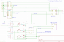
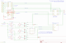
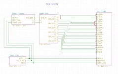
I have sketched it all out in kicad. Hopefully the attached screenshots give you enough information about how this horror-show fits together. The wire placement and join points in the schematic are representative of the wiring topology.
Different grounds everywhere and full of loops - but silent until you stick an antenna on the input.
Hypotheses very welcome.
Different grounds everywhere and full of loops - but silent until you stick an antenna on the input.
Hypotheses very welcome.
Attachments

I'd try connecting a battery operated CD player, FM radio, or MP3 player through the RCA jack to the input. That could prove or disprove a ground loop through a 3rd pin of power cord problem. Obviously you'll have to use a 3.5 stereo phono plug to dual RCA converter cable, which have their own hum problems. Turn volume down to 1/3. Earphone outputs of those appliances can reach 7 VAC and line level input of amps is usually 2 vac max or even .9 v max for some units.
Last edited:
I will try both of those things. What is the differential diagnosis though if it is (not) quiet with a shorted input cable, or attached to a floating source? I don't think the power-ground is the problem; it will hum when connected just to the floating DSP-408. I will confirm that obviously using a shorted input on a long cable.
Next step I think is to reduce the large number of GND/CHASSIS connections to one, and to split the loop formed by the screens of the inputs to the amp modules joining at the differential inputs. That will require I build a regulated supply that's good for >50V input though. In theory I can step down by about 25V per LM317/337 pair so a two-stage series reg should work; I just need to make sure that I don't exceed max 35V between input & output of each stage during turn-on/off transients etc.
Next step I think is to reduce the large number of GND/CHASSIS connections to one, and to split the loop formed by the screens of the inputs to the amp modules joining at the differential inputs. That will require I build a regulated supply that's good for >50V input though. In theory I can step down by about 25V per LM317/337 pair so a two-stage series reg should work; I just need to make sure that I don't exceed max 35V between input & output of each stage during turn-on/off transients etc.
Don't do a solution until you do the tests. A wall transformer may be causing the problem even without a ground pin. Valid shorting plug test is with no cables on it to pick up hum. RCA cables do pick up hum, just not much in 2 meters. You said "sources", there may be ground loops through the various RCA cables. I had to float rings of 12 RCA jacks on my mixer from steel case with o-rings due to hum pickup.
I have undone all the test-hacks and it's roughly back to the configuration as-drawn. I have been reading this guide to ground loops which looks good and I will readily admit that the amp does NOT follow all of its guidance, hence it has a tiny bit of residual noise/buzz with open inputs...
but.
AYFKM.
I think I have isolated the DSP-408 as the source of the hum.
Measurements of the output of a 100W channel, using the FFT function on my cheap siglent CRO:
Any advance on "the DSP is to blame, and I just spent 3 days trying to debug my amplifier that wasn't really broken?" 🙁
In (partial) defence of the DSP-408, the PSU it came with died while sitting on the shelf. I subbed in a random 12V 2A switcher (to replace the cheap-looking noname 12V 1.5A switching it came with), and that could well be the root of the problem - I haven't measured it yet for output noise or common-mode hum or anything. But then, Dayton did supply it with a PSU that died.
I'll try the DSP soon with a benchtop supply, not that I necessarily have any confidence that my benchtop supply is particularly clean.
Argh.
but.
AYFKM.
I think I have isolated the DSP-408 as the source of the hum.
Measurements of the output of a 100W channel, using the FFT function on my cheap siglent CRO:
- Powered off
- Flat noise floor at about -90dBV; this seems to be my CRO's limit at 200mV/div
- With open inputs:
- 10mV offset, 15mV p-p noise, no hum,
- noise floor looks basically the same as when powered off
- With a shorted floating cable:
- same noise level as an open input, no hum
- With a shorted cable, screen connected to screen of another cable:
- same as open input or shorted cable, no hum
- therefore hum does not seem to be due to cross-input loop
- With an open floating cable, it picks up PSU noise from nearby switchers
- 10mV offset, 115mV p-p noise. A mix of 50Hz and HF mostly 16kHz & 32kHz
- touch the cable and it gets really loud, obviously
- Touching an input-shorted cable gives tones at 485Hz=-58dBV and 50Hz=-72dBV: probably poor CMRR on my differential input
- Input plugged into DSP-408 which is floating (no inputs) and powered on:
- square-wave 50Hz at about 340mV p-p
- 50Hz at -18dBV and 150Hz at -30dBV
- 16/32kHz at -52/-40dBV
- DSP input plugged into phone (floating):
- same as with the DSP input floating (-18dBV hum at 50Hz)
- Amplifier input plugged directly into phone (floating)
- no hum. Noise floor is back down to -90dBV
Any advance on "the DSP is to blame, and I just spent 3 days trying to debug my amplifier that wasn't really broken?" 🙁
In (partial) defence of the DSP-408, the PSU it came with died while sitting on the shelf. I subbed in a random 12V 2A switcher (to replace the cheap-looking noname 12V 1.5A switching it came with), and that could well be the root of the problem - I haven't measured it yet for output noise or common-mode hum or anything. But then, Dayton did supply it with a PSU that died.
I'll try the DSP soon with a benchtop supply, not that I necessarily have any confidence that my benchtop supply is particularly clean.
Argh.
OK it's running now in my rack off the benchtop supply. Hum is not zero, but it's way way down. There is no 50Hz component to the DC output of the benchtop supply (according to the CRO FFT) but I suppose there is some sort of capacitive path through these switching supplies which is forming the loop.
Is there any chance that my quite-high impedance inputs (10k) inputs are contributing to this? Would I do better to change the resistors on the differential amp (schematic in very first post) to 2k or so? Can't hurt for johnson noise, at least.
I'll build a little linear supply and evict the bench supply to see if that improves things too. Also don't like having a knob back there which, when turned, can readily cook the DSP with supply overvoltage. If I know my cat, he'll turn it...
OK but do I have an impedance problem? Contributing to my residual hum?
That circuit I suspect merely has better CMRR than mine, though it would want to for containing 3x as much silicon. They're both over 10k per leg for input impedance.
That circuit I suspect merely has better CMRR than mine, though it would want to for containing 3x as much silicon. They're both over 10k per leg for input impedance.
The 24k resistance is simply to suit my very ordinary MM cartridge. The advantage is both input legs being non-inverting and the increased common mode cancellation of the diff amp signals through having very low and equal source impedance and that may remove your residual noise. That said you may find that tacking a 1k resistor across each of the 10k's in your diff amp is a good test of an impedance problem or not.
@laplace I would try ground lifter with bridge rectifier (+ & - shorted and AC & AC shorted, gnd on one shorted end and chassis on another shorted end, with 10R resistor parallel) in your amp chassis, to lift grounds of your LM3xxx and AB 100W amps. You have to use two ground lifter because you have two separate power supply's which are connected to the chassis. Source signal gnd (DSP) is your third point where ground loops are closed.
You have new situation here, not balanced input, but single ended and ground loop is created via these power supply's of amps now. Hope it will help, it is cheap solution and worth to try.
You have new situation here, not balanced input, but single ended and ground loop is created via these power supply's of amps now. Hope it will help, it is cheap solution and worth to try.
Yes, suspected as much. Good tests to prove where problem was. **** power supply in some line level source.Any advance on "the DSP is to blame, and I just spent 3 days trying to debug my amplifier that wasn't really broken?" 🙁
I wouldn't lower input impedance from 10k . I used an amp with >100k input impedance and it didn't hum. Had to be compatible with a 12AX7 preamp cable drive which is about a 250 kohm source. Amp had RCA jack inputs and no differential input stage since op amps were $200 in 1966.
You have XLR inputs available I believed you said. Use twisted pair cable with XLR instead of coaxial RCA cable. In runs longer than 6' it hums less. Stage bands regularly run 100' from sound man in the audience to power amps on stage, with twisted pair and differential drive mixer outputs.
Yes, suspected as much. Good tests to prove where problem was. **** power supply in some line level source.
I wouldn't lower input impedance from 10k . I used an amp with >100k input impedance and it didn't hum. Had to be compatible with a 12AX7 preamp cable drive which is about a 250 kohm source. Amp had RCA jack inputs and no differential input stage since op amps were $200 in 1966.
You have XLR inputs available I believed you said. Use twisted pair cable with XLR instead of coaxial RCA cable. In runs longer than 6' it hums less. Stage bands regularly run 100' from sound man in the audience to power amps on stage, with twisted pair and differential drive mixer outputs.
The physical connectors and input electronics on the amp all assume balanced XLR, so I have recycled my old XLR cables by sticking RCA cables on their source ends.
They are proper woven-screen mic cable with 2 cores of about 0.8mm^2 each. Should be good enough; the only issue is that gain is a bit down but that's OK. Better to have gain at the front of the signal chain than the end 🙂
To check if you have a cross channel ground loop, take a cable and cross connect the L & R inputs. If there is zero hum, you pyobsbluvdont have a cross channel GL prob. Note this is not the same as just plugging s cable into one input and shorting the other end of the cable out. Getting amplifiers quiet can be tough. Good luck 😊
You might find some tips here (see last few slides for debugging methodology)
Ground Loops
Loop Area and Noise
You might find some tips here (see last few slides for debugging methodology)
Ground Loops
Loop Area and Noise
To check if you have a cross channel ground loop, take a cable and cross connect the L & R inputs. If there is zero hum, you pyobsbluvdont have a cross channel GL prob. Note this is not the same as just plugging s cable into one input and shorting the other end of the cable out. Getting amplifiers quiet can be tough. Good luck 😊
You might find some tips here (see last few slides for debugging methodology)
Ground Loops
Loop Area and Noise
Thanks; that was line 4 in the testing and the PDF I linked in the post 🙂
Are you sure your screen and signal lines are not swapped somewhere? When you use just your phone its completely floating so you wont get hum. If you use a mains powered device then you will if the screen and signal lines are swapped.
Last edited:
CMR
So you have a classic ground loop problem.
In every case of ground loops I have dealt with, I find it is a design fault that can be corrected without balanced lines. Being a DIY kit, that raises a red flag to me. Unfortunately, fixing ground loops is half black art and very hard to do in a forum. Even figuring out which unit is at fault can be difficult.
Just a note: Good CMRR requires VERY precise resistor matching. .1% parts and you may want to select. Fortunately, CMRR is not the same as a ground loop problem so unless running 50 or more feet in a noiesy environment, so-so CMRR is fine.
Have you read the discussions of balanced lines on Jensen, THAT, ESP and maybe Self?
So refreshing you are asking about real problems, not the current fad that balanced lines magically cure everything from Covid to world hunger when the DAC is a foot from the amp.OK but do I have an impedance problem? Contributing to my residual hum?
That circuit I suspect merely has better CMRR than mine, though it would want to for containing 3x as much silicon. They're both over 10k per leg for input impedan
So you have a classic ground loop problem.
In every case of ground loops I have dealt with, I find it is a design fault that can be corrected without balanced lines. Being a DIY kit, that raises a red flag to me. Unfortunately, fixing ground loops is half black art and very hard to do in a forum. Even figuring out which unit is at fault can be difficult.
Just a note: Good CMRR requires VERY precise resistor matching. .1% parts and you may want to select. Fortunately, CMRR is not the same as a ground loop problem so unless running 50 or more feet in a noiesy environment, so-so CMRR is fine.
Have you read the discussions of balanced lines on Jensen, THAT, ESP and maybe Self?
CMR
So refreshing you are asking about real problems, not the current fad that balanced lines magically cure everything from Covid to world hunger when the DAC is a foot from the amp.
So you have a classic ground loop problem.
In every case of ground loops I have dealt with, I find it is a design fault that can be corrected without balanced lines. Being a DIY kit, that raises a red flag to me. Unfortunately, fixing ground loops is half black art and very hard to do in a forum. Even figuring out which unit is at fault can be difficult.
Just a note: Good CMRR requires VERY precise resistor matching. .1% parts and you may want to select. Fortunately, CMRR is not the same as a ground loop problem so unless running 50 or more feet in a noiesy environment, so-so CMRR is fine.
Have you read the discussions of balanced lines on Jensen, THAT, ESP and maybe Self?
I built the thing with balanced inputs because it was designed to work with crossovers that have balanced outputs. As you say, no crazy-long lines so I didn't care much for CMRR; the cables are under 50cm in length. I assume only that my average-to-poor CMRR is merely no worse than an unbalanced input 🙂
I've read the Jensen and THAT writings on balanced stuff; I'm only half-way through Doug's power-amp book and haven't read his Small Signal book. As above, I'll not pretend that it has any benefit for my use-case except that it originally made integration a bit easier. This thing doesn't need to work with 100-foot cables draped across a radio-station.
As to the ground loop, I don't think there is one, at least involving the amp. Zero hum with inputs cross-connected etc. It's now installed and running somewhat quietly (can hear hum within about 30cm of woofer); I hope to improve it slightly when I replace the benchtop supply on the DSP and/or replace the DSP with an analogue crossover - a bit more motivated for that now.
I can definitely introduce a loop by attaching USB (DSP via USB shield to PC, to power ground, to signal source, through RCA cable shields, to DSP again), but that doesn't seem to introduce any bad effects.
- Home
- Amplifiers
- Solid State
- Help me with a hum problem?