kipman, as always thanks for your reply
What do I need to modify in the 3E board? I need to remove the clock and then what?
I understand this crystal has 4 solder pads. To which I should solder the MCLK from the USB?
Also, can I reverse this if I solder it back again?
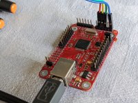
Remove the crystal and connect your external clock to pin 1, the one with the triangle. My crude line drawing shows the PCB connections - the line heading toward the 1701 goes to MCLKI, pin 32. Try to keep the external clock line as short as possible.
As far as reversing the process: the hard part (for me with limited SMD soldering experience) is resoldering the crystal in place. Having the two caps so close to the crystal certainly didn't help. YMMV.
View attachment 1012509
Thanks for your help!
I think I will try it... I also have to remove the resistor, right?
Also, If I wanted to go back to the DSP with it's internal clock, can't just I wire a "bigger" clock and not a SMD?
Kipman's idea seems sensible. Did you try it?
Also, it might help if you could attach a clear pic of how you have wired up the USB and DAC boards. Sometimes the problem can be seen in a pic when words don't describe it as well.
One more thing: if it comes to it, do you have an oscilloscope?
EDIT: What ernperkins suggests might work too. In part, how well it might work depends on how you wire things together considering we are dealing with rather high RF frequencies here. That's why a pic can be so useful for offering helpful advice.
Kipman's idea seems sensible. Did you try it?
Also, it might help if you could attach a clear pic of how you have wired up the USB and DAC boards. Sometimes the problem can be seen in a pic when words don't describe it as well.
One more thing: if it comes to it, do you have an oscilloscope?
EDIT: What ernperkins suggests might work too. In part, how well it might work depends on how you wire things together considering we are dealing with rather high RF frequencies here. That's why a pic can be so useful for offering helpful advice.
Haven't tried yet. I will upload all the pictures I can from the "setup" without removing the clock, maybe I haven't noticed something important.
Don't have an osciloscope.
I thought Kipman and ernperkins recommendations were the same...
I thought Kipman and ernperkins recommendations were the same...
More or less. There are various ways to make the thing work. If I2S is poorly wired that could be main problem. Whether the DSP chip is in slave or master mode has to do with which device is generating I2S clocks (i.e. BCLK, LRCK). The master clock for each device, MCLK, is a separate issue. ASRC inside the DSP chip can be configured to handle I2S clocks from a different MCLK domain. However, usually best to put all devices, USB board, DSP board, and DAC board, on one MCLK domain. That way no ASRC is needed and SQ can be a bit better. That assumes that the MCLK at the dac is a good, very clean, low jitter one. That's why the one shared MCLK source for all devices should be the one at the dac chip. To avoid polluting that clock signal, only copies of it from a clock buffer should be sent to the other devices.
All that MCLK stuff having been said, you should still be able to get the whole system working reasonably well without changing any of the existing master clocks.
Last edited:
I believe you can get your Reflex board to work as a slave, but the ADAU1701 has to be set up correctly. So don't modify your DSP board yet! I'll respond with a full post in a few hours.Because I can make my ADAU1701 work with my REFLEX USB to I2S board.
If I run the DSP as master I get a ton of noise and constant "pops". Tired TDM and I2S. Also tried REFLEX as master and DSP as slave but cant make it work.
Kipman suggested I need to feed MCLK from the REFLEX board to the DSP.
Great! Looking forward to your findings! Tomorrow I will upload all the pictures of the setup, and thank you!!.I believe you can get your Reflex board to work as a slave, but the ADAU1701 has to be set up correctly. So don't modify your DSP board yet! I'll respond with a full post in a few hours.
Last edited:
These are the settings I would try to use the Reflex USB to I2S board as a slave. Perhaps you know this already, but it may be new to others.
ADAU1701 Configuration:
First: Configure SigmaStudio to use the 48 KHz sampling rate.
Second: Configure the I2S ports. This is somewhat convoluted because we need to use the I2S input lines, but want to configure the BCLK and LRCLK lines as outputs to drive the slave. From the 1701 datasheet:
“If an external ADC is connected as a slave to the ADAU1701, use both the input and output port clocks. The OUTPUT_LRCLK (MP10) and OUTPUT_BCLK (MP11) pins must be set to master mode and connected externally to the INPUT_LRCLK (MP4) and INPUT_BCLK (MP5) pins as well as to the external ADC clock input pins. The data is output from the external ADC into the SigmaDSP on one of the four SDATA_INx pins (MP0 to MP3).”
The problem is usually the “and connected externally” condition. Fortunately, the 3e DSP designers accounted for this. Jumper blocks J2 and J3 make the two necessary “wrap around” connections between the output lines and input lines. So:
Reflex USB Card Configuration
Speaker Configuration: 2.0 or 2.0 – 32 bits.
TDM Format: Off (no jumper)
Sync Mode: Slave
I2S Format: According to the “Speaker Configuration” table this board uses I2S mode. Elsewhere this is listed: “By default, the active edge of BCLK is falling (trailing).”
Number of Bits: This is where the Reflex board documentation is a bit hazy to me. All I could find is this statement: “When changing the frequency and bit depth in the OS settings”. So I assume you set up Fs and the number of bits in the OS driver. The 1701 BCLK settings I chose assume Fs = 48 KHz and 24 bits or 32 bits (not 16 bits).
Hardware Connections:
On DSP: Use J5 pins 1 (MP0 / Data_IN_0), 2 (MP5 / BCLK_IN) and 3 (MP4 /LRCLK_IN) and any of the ground pins (any even numbered pin).
Note: Be aware that Figure 2 in the DSP documentation (the one that shows J5 pin assignments) is the view from the bottom of the board. All pin locations are swapped when viewing from the top of the board (see Figure 1 in the DSP documentation).
Also: Grounding issues can cause problems. Run your laptop on battery power when first testing things out. If that works then try it on AC power.
Hope this helps….


ADAU1701 Configuration:
First: Configure SigmaStudio to use the 48 KHz sampling rate.
Second: Configure the I2S ports. This is somewhat convoluted because we need to use the I2S input lines, but want to configure the BCLK and LRCLK lines as outputs to drive the slave. From the 1701 datasheet:
“If an external ADC is connected as a slave to the ADAU1701, use both the input and output port clocks. The OUTPUT_LRCLK (MP10) and OUTPUT_BCLK (MP11) pins must be set to master mode and connected externally to the INPUT_LRCLK (MP4) and INPUT_BCLK (MP5) pins as well as to the external ADC clock input pins. The data is output from the external ADC into the SigmaDSP on one of the four SDATA_INx pins (MP0 to MP3).”
The problem is usually the “and connected externally” condition. Fortunately, the 3e DSP designers accounted for this. Jumper blocks J2 and J3 make the two necessary “wrap around” connections between the output lines and input lines. So:
- Verify jumpers J2 and J3 are installed
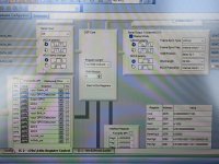
- Configure MP0 as “Input Sdata_in0, MP4 as “Input Lrclk_in, MP5 as “Input Bclk_in, MP10 as “In Lrclk_out” and MP11 as “In Bclk_out”.
- Master mode, LRCLK begins on falling edge, BCLK falling edge
- Frame Sync Type = LRCLK, Frame Sync Freq. = internal clock / 1024, MSB position = delay by 1, Word length = 24 bits, BCLK Frequency = internal clock / 16
Reflex USB Card Configuration
Speaker Configuration: 2.0 or 2.0 – 32 bits.
TDM Format: Off (no jumper)
Sync Mode: Slave
I2S Format: According to the “Speaker Configuration” table this board uses I2S mode. Elsewhere this is listed: “By default, the active edge of BCLK is falling (trailing).”
Number of Bits: This is where the Reflex board documentation is a bit hazy to me. All I could find is this statement: “When changing the frequency and bit depth in the OS settings”. So I assume you set up Fs and the number of bits in the OS driver. The 1701 BCLK settings I chose assume Fs = 48 KHz and 24 bits or 32 bits (not 16 bits).
Hardware Connections:
On DSP: Use J5 pins 1 (MP0 / Data_IN_0), 2 (MP5 / BCLK_IN) and 3 (MP4 /LRCLK_IN) and any of the ground pins (any even numbered pin).
Note: Be aware that Figure 2 in the DSP documentation (the one that shows J5 pin assignments) is the view from the bottom of the board. All pin locations are swapped when viewing from the top of the board (see Figure 1 in the DSP documentation).
Also: Grounding issues can cause problems. Run your laptop on battery power when first testing things out. If that works then try it on AC power.
Hope this helps….
Just perused 1701 datasheet. Looks like it is somewhat different from some of the more general purpose Sigma DSP devices. Apparently no ASRC support in this one. That being the case, the above idea seems like it should work so long as any audio sent to USB card has been resampled as needed to 48kHz by the PC (unless maybe there is SRC on the USB board?). IME Windows doesn't do a great job of audio SRC, but it does work well enough for most non-ultra hi-fi purposes. Not sure about other operating systems.
A W E S O M EThese are the settings I would try to use the Reflex USB to I2S board as a slave. Perhaps you know this already, but it may be new to others.
ADAU1701 Configuration:
First: Configure SigmaStudio to use the 48 KHz sampling rate.
Second: Configure the I2S ports. This is somewhat convoluted because we need to use the I2S input lines, but want to configure the BCLK and LRCLK lines as outputs to drive the slave. From the 1701 datasheet:
“If an external ADC is connected as a slave to the ADAU1701, use both the input and output port clocks. The OUTPUT_LRCLK (MP10) and OUTPUT_BCLK (MP11) pins must be set to master mode and connected externally to the INPUT_LRCLK (MP4) and INPUT_BCLK (MP5) pins as well as to the external ADC clock input pins. The data is output from the external ADC into the SigmaDSP on one of the four SDATA_INx pins (MP0 to MP3).”
The problem is usually the “and connected externally” condition. Fortunately, the 3e DSP designers accounted for this. Jumper blocks J2 and J3 make the two necessary “wrap around” connections between the output lines and input lines. So:
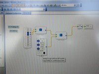
Third: Configure the I2S format and timing parameters.
- Verify jumpers J2 and J3 are installed
- Configure MP0 as “Input Sdata_in0, MP4 as “Input Lrclk_in, MP5 as “Input Bclk_in, MP10 as “In Lrclk_out” and MP11 as “In Bclk_out”.
Note: The 1701 internal clock is 4 times the crystal frequency (12.288 MHz) = 49.152 MHz. Using the above parameters gives a frame frequency of 48 KHz and a BCLK frequency of 3.072 MHz. This timing allows for up to 32 bits per channel so you could set the Reflex USB speaker configuration jumper to “2.0 – 32 bits” if desired. However, the 1701will only use the first 24 bits.
- Master mode, LRCLK begins on falling edge, BCLK falling edge
- Frame Sync Type = LRCLK, Frame Sync Freq. = internal clock / 1024, MSB position = delay by 1, Word length = 24 bits, BCLK Frequency = internal clock / 16
Reflex USB Card Configuration
Speaker Configuration: 2.0 or 2.0 – 32 bits.
TDM Format: Off (no jumper)
Sync Mode: Slave
I2S Format: According to the “Speaker Configuration” table this board uses I2S mode. Elsewhere this is listed: “By default, the active edge of BCLK is falling (trailing).”
Number of Bits: This is where the Reflex board documentation is a bit hazy to me. All I could find is this statement: “When changing the frequency and bit depth in the OS settings”. So I assume you set up Fs and the number of bits in the OS driver. The 1701 BCLK settings I chose assume Fs = 48 KHz and 24 bits or 32 bits (not 16 bits).
Hardware Connections:
On DSP: Use J5 pins 1 (MP0 / Data_IN_0), 2 (MP5 / BCLK_IN) and 3 (MP4 /LRCLK_IN) and any of the ground pins (any even numbered pin).
Note: Be aware that Figure 2 in the DSP documentation (the one that shows J5 pin assignments) is the view from the bottom of the board. All pin locations are swapped when viewing from the top of the board (see Figure 1 in the DSP documentation).
Also: Grounding issues can cause problems. Run your laptop on battery power when first testing things out. If that works then try it on AC power.
Hope this helps….
View attachment 1013078View attachment 1013079
Will try it now.
I already read your post several times, but as much as I love DIY audio, it seems i am not very keen on it.
I focused on this: “If an external ADC is connected as a slave to the ADAU1701, use both the input and output port clocks. The OUTPUT_LRCLK (MP10) and OUTPUT_BCLK (MP11) pins must be set to master mode and connected externally to the INPUT_LRCLK (MP4) and INPUT_BCLK (MP5) pins as well as to the external ADC clock input pins. The data is output from the external ADC into the SigmaDSP on one of the four SDATA_INx pins (MP0 to MP3).”
I can confirm that when trying my ADAU1701 I did not connect MP10 to MP4 and MP11 to MP5 so this alone could be the culprit of the problem.
Posting pics in a few minutes and report how it goes.
If you have the jumpers on the J2 and J3 headers they are connected for you.A W E S O M E
I can confirm that when trying my ADAU1701 I did not connect MP10 to MP4 and MP11 to MP5 so this alone could be the culprit of the problem.
Posting pics in a few minutes and report how it goes.
Tried the configuration. It sounds but sound is choppy (???)
I upload a video of how it sounds. Link here:
I also upload pictures
I upload a video of how it sounds. Link here:
I also upload pictures
Attachments
Last edited:
WOW. It seems to work... It seems to be fixed with BCLK Frequency clock /4Master/slave sync may not be working correctly.
Weird thing is that I am quite sure that the other day I already tried this configuration. Maybe the volume control I had in my DSP scheme was messing things? IDK
Now I will try to add an external I2S DAC for the 3E Audio DSP. Will report in a few minutes.
Last edited:
I tried to use an external PCM5102 DAC with the ADAU1701 while using REFLEX as input, but its a NO NO. Music sounds like Alvin and the Chipmunks.
USB + DSP work OK. My next step is to check if I can connect 2 ADAU 1701 using TDM whiles using Reflex as input.
Weird thing is if I use TDM on Reflex (shorting pin 9) PC recongnize as TDM, but once I change to TDM in serial input on SS sound stops UPDATE: Dont mind, change frame sync type to pulse and it works.
Thank you very much for your help, especially to @ernperkins
Last edited:
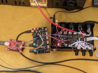
I've got some updates with the REFLEX USB feeding a 3E Audio DSP and then that DSP feeds another 3E Audio DSP for a total of 8 channels.
The thing work, but there is a weird noise in tha background, and IDK if its a clock issue or just that the I2S cables are too long.
Here is the video:
The second DSP is running as slave with the clocks of the first DSP (the one that is connected to the REFLEX)
If I use the DAC of the 1st DSP everything sounds OK without the noise. If I switch to the DAC of the 2nd DSP I get the weird noise.
All ADC are disabled. Wird sound comes with source is AC connected or only battery.
Any clues?
Attachments
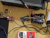
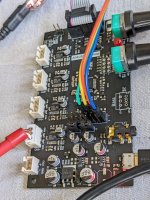
Can't tell from looking at the pics which is the 1st DSP and which is the 2nd?
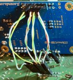
Also, I2S wiring is IMHO poor. Should be one ground wire for each I2S signal. The signals shouldn't be allowed to couple with each other so much. Pic below of I2S wiring that sounds about as good as I could get it. Ground wires are white/green. Also, there are I2S damping resistors on both of the PCBs.
Also, I2S wiring is IMHO poor. Should be one ground wire for each I2S signal. The signals shouldn't be allowed to couple with each other so much. Pic below of I2S wiring that sounds about as good as I could get it. Ground wires are white/green. Also, there are I2S damping resistors on both of the PCBs.
Attachments
It looks like both of your DSPs have their crystal installed. The ADAU1701 data sheet has this statement: "The serial data clocks need to be synchronous with the ADAU1701 master clock input." To follow that statement your 2nd (slave) DSP needs to use the same MCLK signal as the 1st (master) DSP. Which means (as you probably know) removing the crystal in the 2nd DSP and then somehow routing the MCLK from the master to the slave. Certainly not for the faint of heart! If 3e Audio had brought out MCLK to a header it would be relatively simple, but they didn't.
Can't tell from looking at the pics which is the 1st DSP and which is the 2nd?
Also, I2S wiring is IMHO poor. Should be one ground wire for each I2S signal. The signals shouldn't be allowed to couple with each other so much. Pic below of I2S wiring that sounds about as good as I could get it. Ground wires are white/green. Also, there are I2S damping resistors on both of the PCBs.
It looks like both of your DSPs have their crystal installed. The ADAU1701 data sheet has this statement: "The serial data clocks need to be synchronous with the ADAU1701 master clock input." To follow that statement your 2nd (slave) DSP needs to use the same MCLK signal as the 1st (master) DSP. Which means (as you probably know) removing the crystal in the 2nd DSP and then somehow routing the MCLK from the master to the slave. Certainly not for the faint of heart! If 3e Audio had brought out MCLK to a header it would be relatively simple, but they didn't.
The DSP on the metal case is the "slave". Yes, the wiring is done very poorly and just to check if it worked. Thank for the picture, is very illustrative and I will proceed accordingly.
Yes, both DSP have the crystal installed. I thought I would run the slave DSP without re routing the MCLK and removing J2 and J3 would be enough...
I also tried running dual DSP but with analog input (instead of I2S) and it runned properly without any problem.
It looks like both of your DSPs have their crystal installed. The ADAU1701 data sheet has this statement: "The serial data clocks need to be synchronous with the ADAU1701 master clock input." To follow that statement your 2nd (slave) DSP needs to use the same MCLK signal as the 1st (master) DSP. Which means (as you probably know) removing the crystal in the 2nd DSP and then somehow routing the MCLK from the master to the slave. Certainly not for the faint of heart! If 3e Audio had brought out MCLK to a header it would be relatively simple, but they didn't.
I made better I2S cables, shorter and each of DATA, BCLK & LCLK twisted with a GRND and then foiled in aluminum.
USB to 1st DSP sounds very good. Feeding the 2nd DSP clearly has a clocking problem, so...
Any precautions before removing the crystal from the 2nd DSP? Like maximum length of the cable from one DSP to another? Is there any way of removing both crystals and installing a better one for both DSPs?
Cheers
- Home
- Source & Line
- Digital Line Level
- USB to I2S for the 3e audio DSP board?