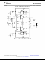
Hi all, it’s been awhile since I posted, so if I’ve missed something or a pertinent thread I apologize. Anyhow, I got myself some 4 ohm speakers for Christmas and I’ve been using a standard LM3886 amp with a single chip for my 8 ohm but I’m planning on building an amp with two LM3886 paralleled per channel. I’m using the example parallel circuit in the LM4780 datasheet, and on the output it shows a 0.1 ohm 3W resistor on both chips. I understand it’s purpose there, but it doesn’t seem like 3W is enough for such a low impedance resistor on the output. Am I missing something?
Attachments
The resistor is 40 times lower than the load assuming matching LM3886 chips. The resistor will see 1/40 of the output power. 3 W should be OK.
Don't forget to use 0.1% precision resistors for Rf1, Ri1, Rf2 and Ri2 if you plan to use it in parallel mode.
Total brain fart…..I was only considering power going into the resistors. Duh. Thanks!The resistor is 40 times lower than the load assuming matching LM3886 chips. The resistor will see 1/40 of the output power. 3 W should be OK.
Thanks for the heads up, but I actually use a high-end multimeter with 4-wire resistance measurement to get nearly perfect matches from a batch of 20-30 1% resistors. 0.1% resistors would probably be easier but I already have the 1% resistors and ability to closely match them.Don't forget to use 0.1% precision resistors for Rf1, Ri1, Rf2 and Ri2 if you plan to use it in parallel mode.
I do not think it is super critical to match the resistors. The resistors exist in case there is a mismatch in the amplifiers as far as gain or offset. 5-10% is probably good enough.
Edit, sorry I did not read closely. Mayching does not matter for the .1 ohm resistors.
Edit, sorry I did not read closely. Mayching does not matter for the .1 ohm resistors.
Last edited:
Matching gain is essential.
And even so, paralleling perfect voltage sources is nonsense to me; at best, an accident waiting to happen.
And even so, paralleling perfect voltage sources is nonsense to me; at best, an accident waiting to happen.
Matching the gain of the two amps will lead to better performance. Matching the ballast resistors is not necessary. As pointed out above, they're there to allow the two amp halves to have different voltage offsets. The ballast resistors should be a type with a low temperature coefficient for best performance.
Tom
Tom
I heard this before and I think is wrong .Thanks for the heads up, but I actually use a high-end multimeter with 4-wire resistance measurement to get nearly perfect matches from a batch of 20-30 1% resistors. 0.1% resistors would probably be easier but I already have the 1% resistors and ability to closely match them.
True that 7^2*0.1 = 4.9. Also true that 11^2*0.1 = 12.1. Recall, the LM3886 can deliver 11 A typical so that would be even more worst case than the 7 A.LM3886 current limit is 7A.
Worst case power into 0.1R is 4.9W.
However... With a 4 Ω speaker and ±35-36 V supply rails, each LM3886 delivers 36/(4*2) = 4.5 A. 4.5^2*0.1 = 2.02 W. This assumes DC operation and zero voltage drop across the LM3886. But it gets better.
If we assume sine wave operation, each 0.1 Ω resistor sees (4.5/sqrt(2))^2*0.1 = 1.01 W.
Few of us listen to sine waves for any length of time. Rather we listen to sums of sine waves in the form of music. It's pretty safe to assume that with music signal, each of those 0.1 Ω resistors dissipates no more than 300-400 mW even with the amp running at clipping levels.
Tom

Can you expand what is wrong with it?I heard this before and I think is wrong .
Great, thank you for the confirmation.Matching the gain of the two amps will lead to better performance. Matching the ballast resistors is not necessary. As pointed out above, they're there to allow the two amp halves to have different voltage offsets. The ballast resistors should be a type with a low temperature coefficient for best performance.
Tom
Awesome explanation, thanks!!True that 7^2*0.1 = 4.9. Also true that 11^2*0.1 = 12.1. Recall, the LM3886 can deliver 11 A typical so that would be even more worst case than the 7 A.
However... With a 4 Ω speaker and ±35-36 V supply rails, each LM3886 delivers 36/(4*2) = 4.5 A. 4.5^2*0.1 = 2.02 W. This assumes DC operation and zero voltage drop across the LM3886. But it gets better.
If we assume sine wave operation, each 0.1 Ω resistor sees (4.5/sqrt(2))^2*0.1 = 1.01 W.
Few of us listen to sine waves for any length of time. Rather we listen to sums of sine waves in the form of music. It's pretty safe to assume that with music signal, each of those 0.1 Ω resistors dissipates no more than 300-400 mW even with the amp running at clipping levels.
Tom
What I wrote is from personal expirience when I noticed difference in output voltage on IC's and after better reading of the datasheet solved the problem.
Resistor which balance output current is not so critical and I leaved it as it is (0.1ohm, or what ever value close to that, I use 0.2 ohm). After that there are no excessive heat on IC's LM3886.
How much I built of this amplifiers after this? About 5 stereo parallel amps were built this way on rail voltage of +/-38V and they deliver about 120W on 4ohm load. Working fine and much better than some known brands. Now I listening that amp sound.
Amp boards are not expensive one, chinese, but upgraded with resistors of 0.1% tolerance and with much better caps. So, what tom said is absolute correct.
- Home
- Amplifiers
- Chip Amps
- Paralleling LM3886 output resistor question