Good Evening,
I have a LM1875 running single supply on a 24V SMPS which seems to be hitting the rails and clipping at about 17v (peak to peak) using a 400hz sine wave.
The chip is receiving 21.4v after regulation (LM317t) and while under load. How close can you get to the rails before distortion is expected?

Even with it biased at 10v, i thought it should get 20v without clipping. Is there anything i could be missing to cause this?
I would also assume that getting an output of 6v RMS on a 8ohm load would be pulling roughly 750ma, but it seems to be much lower.

Any help would be gratefully appreciated 🙂
I have a LM1875 running single supply on a 24V SMPS which seems to be hitting the rails and clipping at about 17v (peak to peak) using a 400hz sine wave.
The chip is receiving 21.4v after regulation (LM317t) and while under load. How close can you get to the rails before distortion is expected?
Even with it biased at 10v, i thought it should get 20v without clipping. Is there anything i could be missing to cause this?
I would also assume that getting an output of 6v RMS on a 8ohm load would be pulling roughly 750ma, but it seems to be much lower.
Any help would be gratefully appreciated 🙂
First thoughts...
A 24volt smps and a reg set to 21.4 volts leaves little headroom. Have you looked at the supply on the scope to make sure it is clean when under load?
The current in the 8 ohm load will be as you say, around 750ma, however the PSU current will appear less (as an rms value) because the current draw from the PSU does not resemble anything like a sine wave.
17.1v peak/peak from a 21.4 volt rail doesn't sound to bad, it is swinging to within a couple of volts of 0 and rail voltage.
First thoughts...
A 24volt smps and a reg set to 21.4 volts leaves little headroom. Have you looked at the supply on the scope to make sure it is clean when under load?
The current in the 8 ohm load will be as you say, around 750ma, however the PSU current will appear less (as an rms value) because the current draw from the PSU does not resemble anything like a sine wave.
17.1v peak/peak from a 21.4 volt rail doesn't sound to bad, it is swinging to within a couple of volts of 0 and rail voltage.
Thanks Mooly,
I think sometimes the different values or measurements used might be throwing me off a bit.
Could you explain the PSU current a little more (or even a link)? I understand that RMS is the DC "equivalent" for AC wave forms as they aren't a sine wave, but i assumed that the 750ma i got by ohms law would be RMS and I would expect to measure very close to the same amount over the PSU's DC.
Thanks as always for your patience.
Look at Fig.5 on the LM1875 data sheet. You are getting what the chip can do with a single +21V supply or a dual +/- 10.5V.
And that only delivers about 5 Watts RMS to the 8 ohm load.
If your application needs more power, you simply need a higher voltage power supply.
And that only delivers about 5 Watts RMS to the 8 ohm load.
If your application needs more power, you simply need a higher voltage power supply.
Attachments
I can't just think of a link that explains it tbh.
The load current calculates as expected for a sine wave. The power supply current depends to some extent on the amp and its quiescent current draw. The current in the output stage of the amp looks like half wave pulses.
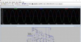
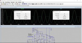
Here is a simulation of a class B single rail amp delivering 6 volts rms into 8 ohm. The load current is 750ma. The 'rms' value of the output transistor current is just over 500ma.
This shows the load current and the output transistor current. Second image is the supply current and load current with some values showing.


Look at Fig.5 on the LM1875 data sheet. You are getting what the chip can do with a single +21V supply or a dual +/- 10.5V.
And that only delivers about 5 Watts RMS to the 8 ohm load.
If your application needs more power, you simply need a higher voltage power supply.
Thanks mate. Tbh 5w is my "target" but i believe the misunderstandings on the calculation is to blame 😊
I can explain it without a link 😉Thanks Mooly,
I think sometimes the different values or measurements used might be throwing me off a bit.
Could you explain the PSU current a little more (or even a link)? I understand that RMS is the DC "equivalent" for AC wave forms as they aren't a sine wave, but i assumed that the 750ma i got by ohms law would be RMS and I would expect to measure very close to the same amount over the PSU's DC.
Thanks as always for your patience.
With a single supply, effective load across it terminals, with an amp delivering full sinewave, it "sees" :
PS load=2 Pi (speaker) Load so it sees:
2 * 3.14 * 8 ohm=50 ohm
PS effective/net/average (we are talking a DC equivalent here) current= 21V/50r=0.42A
In practice, slightly less, because sinewave won´t swing to full 21Vpp but about 17-18Vpp (at best).
Losing 2 V per rail (here +V and ground) is actually very good performance, no doubt LM1875 was highly tweaked when designed.
In "large" amps, count about 4V loss from each rail for a conservative "reality adjustment".
24V raw, even lower 21V regulated is low for what an LM1875 can use, try at least 35-40V and we are talking.
Even raw 50V from a conventional supply is fine.
Always into 8 ohm.
Wow thanks. Makes it make alot more sense. I think I'll look at getting a larger supply to give the amp more headroom and bump up the amps output. Thanks again
Why not just skip the regulators and run the LM1875 directly from the SMPS?
Interestingly the output swing isn't specified in the LM1875 data sheet. But from the circuit diagram on page 6 of the data sheet, I'd expect the output to start to limit around 3*Vbe from the positive rail. That's around 2 V. So the largest sine wave supported by a single 21 V supply would be around 21-4 = 17 Vpp.
Tom
Logically there is a 0.707 in there. 0.707*0.750 is 0.530. Your 500mA finger-count is a bit low, your 0.0538 (on sim V1) is high by the amount of the driver current.The load current is 750ma. The 'rms' value of the output transistor current is just over 500ma.
Figure a sine audio amp "acts like" a resistor 6X higher than the load. 8Ω acts-like 50Ω, to a good approximation. My "6" is really a blend of Pi and RootTwo, with some integer factors.
The other way I have to calculate this (credits to Doug Self I think) are to just calculate the peak load current which for 6 volts rms into 8 ohm would be 1.06 amp peak. Divide that peak result by pi and that will give the average current which is 0.337 amp which is the average current the PSU needs to supply to support that output level into that load impedance. For the simulation that figure agrees very closely by the looks of it. The sim had the bias generator set to give zero bias current and the current draw of the amp in the sim is just 3.05 milliamps. Wow that's low 😉
Of course the extra bits and bobs that any particular circuit draws has to be figured in as PRR suggests. For a chip amp with minimal quiescent current draw the calculated figure should be pretty close to the mark.
Of course the extra bits and bobs that any particular circuit draws has to be figured in as PRR suggests. For a chip amp with minimal quiescent current draw the calculated figure should be pretty close to the mark.
For LM1875, max. volts rating is 64 (+/- 32V), and 80% of that is about 50V, safe or normal voltage.
Bump it up, and use a largish cap, 4700 or 6800 to keep power reserve.
24V is 2030 territory.
Philips used 28V AC in the Powerhouse series amp section, 14V AC for the tuner / selector / radio / pre amp / cassette, the chips were uPC 1238, (substitute was TDA 2030), later models had Matsushita AN7125 or AN7161.
You can work out the DC voltages.
- Home
- Amplifiers
- Chip Amps
- LM1875 Early Clipping