Hi everyone
I recently built a small amp mostly from parts i already had, the whole thing was simulated in ltspice and results were satisfying. The amp works and sounds fine however power output is lacking, my speakers are efficient (~94db) but i find that i have to turn up the volume quite a bit before i get satisfying output. So i went ahead and measured it on my newly acquired scope which showed me that i barely get 2W of output power.
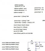
Simulation:

This gives me 4.8W at 1.3% THD. The output transformer model i used comes from Robert McLean's excel spreadsheet.
Reality:

This is just before clipping, fed with 2.2Vpp at 1KHz from a signal generator. Load are two 50W 16 Ohm resistors in parallel. My math here is as follows: 11.4Vpp * 0.3535 = 4.0299. 4.0299² = 16.24. 16.24 / 8 = 2.03W.
So my question is, did i do anything wrong here? Is my basic circuit and measurements correct? I'm still quite new to tubes so there might be an obvious mistake somewhere that i just couldn't figure out.
I do realize that output transformers in ltspice aren't really that accurate as they have no losses and generate no distortion but the power output shouldn't be that far off right?
I recently built a small amp mostly from parts i already had, the whole thing was simulated in ltspice and results were satisfying. The amp works and sounds fine however power output is lacking, my speakers are efficient (~94db) but i find that i have to turn up the volume quite a bit before i get satisfying output. So i went ahead and measured it on my newly acquired scope which showed me that i barely get 2W of output power.
Simulation:
This gives me 4.8W at 1.3% THD. The output transformer model i used comes from Robert McLean's excel spreadsheet.
Reality:
This is just before clipping, fed with 2.2Vpp at 1KHz from a signal generator. Load are two 50W 16 Ohm resistors in parallel. My math here is as follows: 11.4Vpp * 0.3535 = 4.0299. 4.0299² = 16.24. 16.24 / 8 = 2.03W.
So my question is, did i do anything wrong here? Is my basic circuit and measurements correct? I'm still quite new to tubes so there might be an obvious mistake somewhere that i just couldn't figure out.
I do realize that output transformers in ltspice aren't really that accurate as they have no losses and generate no distortion but the power output shouldn't be that far off right?
It seems to me that B+ is quite low for the 5K primary. The 6P15 can handle 12W, and higher voltage (300+).
Can you post the .asy file to run it?
Can you post the .asy file to run it?
I see, the thing is i'm using a switch mode power supply in this amp, 250V is all it can provide..It seems to me that B+ is quite low for the 5K primary. The 6P15 can handle 12W, and higher voltage (300+).
Can you post the .asy file to run it?
I attached the sim file and added the 5k transformer model in case you don't have it.
Attachments
I thought that R9 should be around 1...10Meg...it doesn't really work as an inverted input feedback as it makes a divider with R4 and indeed the voltage supply might be a bit low for the 6p15p impedance .
It seeps to be matching more or less the simulation, I get 4.454 RMS output voltage.
What can you change in the design? If you are married to the 6P15, 250V, then trying 2 6P15 in parallel and a lower impedance OPT will help.
What can you change in the design? If you are married to the 6P15, 250V, then trying 2 6P15 in parallel and a lower impedance OPT will help.
Open look gain and distortion will go up. Of you have a small 48v power supply you could add it to the 250V one, getting to ~300.I'd remove R9 first...
alright i disconnected r9, i get the same output power but at only 600mVpp input, more than that and it starts clipping heavily.I'd remove R9 first...
I see, well since this is just an experimental amp from spare parts i'll probably just use it this way, 2W is enough for normal listening. May also try connecting it in triode mode without feedback but that'll probably cut the power in half.It seeps to be matching more or less the simulation, I get 4.454 RMS output voltage.
What can you change in the design? If you are married to the 6P15, 250V, then trying 2 6P15 in parallel and a lower impedance OPT will help.
I didn't realize that at 5K B+ would be too low, is there a way to calculate required (or "optimal") B+ when using an OT with x impedance? I did have a look at the loadline calculator which does say i should be able to get 4W at 240V/40mA.
Test which clips first, the driver tube, or the output tube?
The typical Schade circuit you have has the driver tube cathode un-bypassed (that is normal for Schade configuration, to get the plate impedance increased).
But the driver R5 and R9 (and R4) limit how far the driver can swing.
The driver plate current has to drive those 3 resistors to 2X the output tube cathode bias voltage.
Driver +/-Swing needs, + swing = absolute (unsigned) Bias voltage, and absolute (unsigned) - swing - Bias voltage
I do not use simulation programs.
I do the math myself, make mistakes, correct myself. But the proof is in the real circuit's performance.
Hi Disso,
I changed your simulation a little to use my LTspice hierarchical OPT
I used the parameters from your model: Rp=5k Lp=40 Rdc=56 K=0.9995.
experimenting with different impedance OPT is now very easy: f.i. just change the parameter Rp=5k to Rp=3k5.
models:
https://www.diyaudio.com/community/attachments/se_test-el34-zip.1006158/
Attachments
This ^ check the scope pattern on the grid and the output to figure out which one is clipping first.Test which clips first, the driver tube, or the output tube?
11.4V pp at the secondary is about 91V pp at the primary. That should be no problem with a 250V HT. So you must be running out of current. What is the dc volts across the 100 ohm cathode resistor?
Cheers
Ian
Cheers
Ian
With the real OPT parameters: 2.37W 1.25%

Use this parameters (see *.asc) for transient simulations.
Use this parameters (see *.asc) for transient simulations.
Attachments
Last edited:
Test which clips first, the driver tube, or the output tube?
At about 1.6Vpp input the waveform at the output tube grid becomes triangular, so it seems to be the driver clipping first.
11.4V pp at the secondary is about 91V pp at the primary. That should be no problem with a 250V HT. So you must be running out of current. What is the dc volts across the 100 ohm cathode resistor?
Cheers
Ian
4.2V so should be fine?
Hi Disso,
I changed your simulation a little to use my LTspice hierarchical OPT
I used the parameters from your model: Rp=5k Lp=40 Rdc=56 K=0.9995.
experimenting with different impedance OPT is now very easy: f.i. just change the parameter Rp=5k to Rp=3k5.
models:
https://www.diyaudio.com/community/attachments/se_test-el34-zip.1006158/
thanks, that's very useful!
With the real OPT parameters: 2.37W 1.25%
View attachment 1012175
Use this parameters (see *.asc) for transient simulations.
Thanks, this looks more realistic. Using your OPT i can get 4W at 5.6% THD with R5=10K, R6=220R, R9=150K. Sadly i can't test it as i don't have resistors with those values.
To get the output power in my previous simulations i just looked at the dissipation of my 8 ohm load resistor but i guess that's not the correct way of doing it because ltspice does not use the rms voltage in that case.
Yea that seems to have been my mistake, if i just measure the voltage swing at OT secondary in ltspice and apply the same math i applied to my real world measurements i end up with a similar value...
thanks everyone for your help!
thanks everyone for your help!
All that. No comments on the circuit as I don't do tubes, but Spice transformer models are notoriously poor.
Spice input voltage is PEAK TO PEAK, not RMS, so that fools some.
Look at that .four command further. Read up on how samples and frequency have to be mathematically linked or you get bogus results. I do 10 harmonics for 1K input. You did not set your significant bits.
I am not saying my parameters are correct, but this is the best I have come up with
Attachments
Discussion aside about the most you can expect from an optimized implementation is about 4.5 - 5Wrms. The value of R8 seems excessively high to me, try something like 220 - 470 ohms and see what happens. Note that in a perfect world your driver would show pretty close to 0Vac since it you have applied inverting voltage feedback around the output stage and you are measuring at the summing point.
I would check in the menus I am pretty sure this Rigol scope will give you the option of displaying RMS volts along with the other information at the bottom of the screen.
I would check in the menus I am pretty sure this Rigol scope will give you the option of displaying RMS volts along with the other information at the bottom of the screen.
Last edited:
Well done, the screen resister is far too high. Reduce it to a 100R CC.Discussion aside about the most you can expect from an optimized implementation is about 4.5 - 5Wrms. The value of R8 seems excessively high to me, try something like 220 - 470 ohms and see what happens. Note that in a perfect world your driver would show pretty close to 0Vac since it you have applied inverting voltage feedback around the output stage and you are measuring at the summing point.
I would check in the menus I am pretty sure this Rigol scope will give you the option of displaying RMS volts along with the other information at the bottom of the screen.
Or bypass R8 as is with 100 mFarad. Power will go up some, but don't expect much using that PS.
Chances are it will sag a lot when the screen is fed properly.
I would not generalise about all transformer models being poor. Admittedly I have only compared real hardware results for the Hammond 1650HA, the model I used almost perfectly matched the real amp results, including the instability under heavy gNF.All that. No comments on the circuit as I don't do tubes, but Spice transformer models are notoriously poor.
Spice input voltage is PEAK TO PEAK, not RMS, so that fools some.
Look at that .four command further. Read up on how samples and frequency have to be mathematically linked or you get bogus results. I do 10 harmonics for 1K input. You did not set your significant bits.
I am not saying my parameters are correct, but this is the best I have come up with
Glad that works out. I am only assuming the cautions I found on the LTSpice forums. I was not that lucky in my attempts to model an ignition coil. My attempts to model the dynamics of a spark plug during the ignition cycle were totally a bust. My amplifier models calculate THD about 100 times better than reality.I would not generalise about all transformer models being poor. Admittedly I have only compared real hardware results for the Hammond 1650HA, the model I used almost perfectly matched the real amp results, including the instability under heavy gNF.
- Home
- Amplifiers
- Tubes / Valves
- ltspice vs reality - what am i doing wrong?