Happy New Year !
I have some #45 and 6B4G, and have DIY-ed several Push Pull amps with
RC phase inverter and interstage transformer (LL1660S) as splitter.
They don't sound as dynamic (or good ! playing symphonic music)
as one SET 300B that I built.
Still, I want to improve my Push Pull #45 amps. 🙂
Reading this article
"Phase Inversion Circuits" by John W. Straede in Radio-Craft, 1948.
https://dalmura.com.au/static/Phase Inversion Circuits Radio Craft 1948.pdf
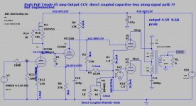
leads me to consider a iron-less and coupling-capacitor-less PP amp.
The basic idea is using CCS for self-splitting, and direct-coupling technique
to eliminate the coupling capacitor.
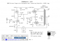
Here is the first take of the circuit for LTspice.
There are flaws:
bias stability needs work, splitting is not perfect, and safety issue.
10M45S is there just for the purpose of simulation.
Comments are welcome !
I have some #45 and 6B4G, and have DIY-ed several Push Pull amps with
RC phase inverter and interstage transformer (LL1660S) as splitter.
They don't sound as dynamic (or good ! playing symphonic music)
as one SET 300B that I built.
Still, I want to improve my Push Pull #45 amps. 🙂
Reading this article
"Phase Inversion Circuits" by John W. Straede in Radio-Craft, 1948.
https://dalmura.com.au/static/Phase Inversion Circuits Radio Craft 1948.pdf
leads me to consider a iron-less and coupling-capacitor-less PP amp.
The basic idea is using CCS for self-splitting, and direct-coupling technique
to eliminate the coupling capacitor.
Here is the first take of the circuit for LTspice.
There are flaws:
bias stability needs work, splitting is not perfect, and safety issue.
10M45S is there just for the purpose of simulation.
Comments are welcome !
Attachments
fossa,
1. M2 maximum voltage might be exceeded before the type 45 tubes filaments warm up (low current draw).
450V B+ will be more than 450V, especially if you use solid state rectifiers, which turn on instantly.
Use the IXYS 900V part.
2. You seem to be afraid of using coupling caps.
So you DC couple the driver to the 45 tubes. That can work, but requires more careful adjustment, and can vary with changing power mains voltage, and as tubes age.
3. Your schematic has no way to balance the two 45 quiescent DC plate currents, except to vary the 163V grid voltage on the one 45 tube.
Push Pull output transformers do not like un-balanced plate currents.
4. The constant current sink, M1, with one tube cut off, will limit the other tube's max current to 2X its quiescent current.
And M1 will also reduce the gain of each 45 tube to about 1/2 of what it would be in a non self inverting stage. That requires lots more drive voltage from the driver tube.
Last edited:
A fullt dc coupled power amplifier is an excellent ambition. If you can also arrange for the NFB to operate down to dc this will do wonders for amplifier stability.Why try to reinvent the wheel ...
Cheers
Ian
It is a valve amplifier and they do not work well balancing output DC levels.A fullt dc coupled power amplifier is an excellent ambition. If you can also arrange for the NFB to operate down to dc this will do wonders for amplifier stability.
Cheers
Ian
I used to work with valve computers, (adding machines), that had over 300 12at7s in them and was failing daily due to voltages drifting. That is why we now use solid state for precise DC levels and valves for a wonderful logrithmic sound.
It may work for a short while but will constantly require adjustments.
It is a valve amplifier and they do not work well balancing output DC levels.
Valve op amps operating down to dc existed 70 years or more ago. NFB will stabilise dc conditions as much as ac ones.
Valves do not have a logarithmic transfer function - semiconductors do. Valves have a 3/2 power transfer function (Look up Child's law)I used to work with valve computers, (adding machines), that had over 300 12at7s in them and was failing daily due to voltages drifting. That is why we now use solid state for precise DC levels and valves for a wonderful logrithmic sound.
It may work for a short while but will constantly require adjustments.
Child's Law
Cheers
Ian
By the way, anyone who thinks you cannot do much at dc with tunes should read this:
https://www.analog.com/media/en/training-seminars/design-handbooks/Op-Amp-Applications/SectionH.pdf
Cheers
ian
https://www.analog.com/media/en/training-seminars/design-handbooks/Op-Amp-Applications/SectionH.pdf
Cheers
ian
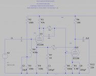
Post #9 . . . Very interesting!
2 tubes, DC coupled, and it has 3 poles 'within' the negative feedback loop, C1, C3, and C6.
Post # 6 . . . the GM70 amplifier is DC Coupled, but the first stage plate has a choke load.
It does not 'go down' to DC (unless you count 10's of dB attenuation versus mid frequencies.
And the output tube is DC coupled all the way to the output transformer, where all DC 'stops' from the output.
If you listen to LP records, the 10Hz phono cartridge/tonearm resonance, and the 3Hz record warp may get you every time (watch the woofer cone dance).
Last edited:
Post 9 shows AC coupling; C4, C5 and C3.
Not sure I would like half HT/B+ on my input source at startup/power down.
Not sure I would like half HT/B+ on my input source at startup/power down.
1. Nobody said Post # 9 amplifier had DC frequency response.
Correct, C4 and C5 prevent that.
C3 does not prevent DC frequency response of the two DC coupled stages.
C3 is in parallel with a resistor, it causes high frequencies to 'lead' the low frequencies, but in no way prevents DC coupling of the two stages.
2. Post # 7, Childs Law applies to Triode vacuum tubes.
I believe that Tetrodes, Pentodes, and Beam Power tubes do not conform according to Childs Law (unless you 'Triode Wire' them).
. . . I would love to be corrected on this, I think only Triodes are according to the 3/2 exponent.
Last edited:
Yes, I agree, inductive load has disadvantages, so it is better to use a resistor load:Post # 6 . . . the GM70 amplifier is DC Coupled, but the first stage plate has a choke load.
It does not 'go down' to DC (unless you count 10's of dB attenuation versus mid frequencies.
And the output tube is DC coupled all the way to the output transformer, where all DC 'stops' from the output.
If you listen to LP records, the 10Hz phono cartridge/tonearm resonance, and the 3Hz record warp may get you every time (watch the woofer cone dance).
Caddock mp930 vs aluminium housed resistor
I think that Childs Law most accurately applies to Vacuum Diodes (3/2 power).
Grid(s), even at a fixed voltage change those curves.
Triode plates tend to be resistive.
Tetrodes, Pentodes, and Beam Power plates are closer to being a Current Sink, than Triodes are.
All Generalizations Have Exceptions.
Grid(s), even at a fixed voltage change those curves.
Triode plates tend to be resistive.
Tetrodes, Pentodes, and Beam Power plates are closer to being a Current Sink, than Triodes are.
All Generalizations Have Exceptions.
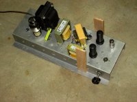
Like many I was curious about these self inverting power stages. The circuit has been in use since before WW2.
So if I'm going to Talk The Talk I better Walk The Walk.
About 15 yrs ago I ran some simulations, it looked like better results could be had by using a choke tail instead of a simple resister.
But simulations often mislead, this was one of them.
Using a well worn Mule I bench tested several versions of Resister, FET & Choke Tails. And combinations.
The best results were in fact those with the choke tail. But none of the circuits were able to deliver more than half that using a normal phase inversion.
The D% results were in general poor. So in no particular order here are some of the test results. The basic circuit is PP 6V6s. The OPT an H125E.
And an example of a DC coupled PP stage that does work. Much of this work was put on DIY 3 yrs ago.
Attachments
-
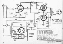
 117L7GT PP Amplifier with Self Inversion.jpg431.9 KB · Views: 276
 -
 IMG_2081 Self Inverting Amp 14H E.jpg281.6 KB · Views: 213
 -
 Self Inverting Amplifier Performance Summary.jpg87.7 KB · Views: 229
 -
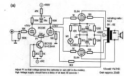 EL84 PP Direct Coupled.jpg119.8 KB · Views: 280
 -
 PP 6V6 Self Inverting Amplifier.jpg51 KB · Views: 286
 -
 6SL7-SRPP-KT77-Push-Pull-Tube-Amp-CCS.png10.6 KB · Views: 297
 -
 6bw6_driver_el84pp_simple.gif17.1 KB · Views: 288
You want to understand that a triode plate has two functions: attract and collect.I believe that Tetrodes, Pentodes, and Beam Power tubes do not conform according to Childs Law
In the tet+rodes these functions are handled by different electrodes.
When you plot cathode current against either G1 or G2 screen voltage it looks a lot like Childs Law (except in the wiggly low-V low-I zone).
The problem with the output stage also doing the phase splitting is that you lose a lot of gain, so you lose power output.
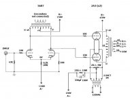
DC-coupling can be accomplished by using a center-tapped choke as the plate loads for an LTP, then 'stacking' the DC power supplies.
The driver stage is grounded to 0V while the output stage 'ground' is the driver stage B+.
The output stage is cathode biased so that the output tubes' cathodes are lifted above the virtual ground/driver stage B+ voltage.
It's harder to explain than it is to show it....
Attachments

Post #9 was not meant to be an exemplar. It was just something I knocked together about 10 years ago to see if it could be done. Poles in the loop are not problematic per se. It depends how they are distributed. In tube amplifier, zeros in the loop are usually the problem.
Cheers
Ian
Cheers
Ian
That cct would perform very well indeed. Some folks object to the large power wasting cathode resistor.The problem with the output stage also doing the phase splitting is that you lose a lot of gain, so you lose power output.
DC-coupling can be accomplished by using a center-tapped choke as the plate loads for an LTP, then 'stacking' the DC power supplies.
The driver stage is grounded to 0V while the output stage 'ground' is the driver stage B+.
The output stage is cathode biased so that the output tubes' cathodes are lifted above the virtual ground/driver stage B+ voltage.
It's harder to explain than it is to show it....
But that is what all tubes do with ease.
PRR,
Yes, in a tetrode, the screen can act as a plate.
But only if you either disconnect the plate, or connect the screen and plate together.
I built an amplifier with a 4-65A, a real tetrode, for those who may not know a 6L6 is not a tetrode (not you PRR).
I connected the 5k output transformer to the 4-65A screen. The plate was left disconnected.
Even when the output current was tested at the B+ voltage of about 390V, tying the plate to the screen did not significantly increase the output current. That tube really wants the plate voltage to be 2X, 3X, or more Volts than the screen voltage.
I used an ECC99 driving a 1:1 interstage transformer to drive the 4-65A.
The screen current was adjusted by the self bias resistor so that the screen voltage x the screen current gave 10 Watts screen dissipation,
(its maximum rating).
With the plate disconnected, the plate was cold (not dissipating its 65 Watt rating) and so the cold plate did not add to the screen heating; keeping the screen very safe at its 10 Watt rating.
For safety, the plate was grounded, so grabbing the plate cap was safe and OK.
Yes, in my special case amplifier, the 4-65 screen acted exactly like a "plate" when the plate was disconnected.
But if I had much higher B+, and had only the plate driving the 5k output, plus if I had the screen connected to a constant voltage supply (as the 4-65A was designed for), then the screen would no longer act like a plate, its screen current versus grid 1 voltage and plate voltage would be different, versus the way I used in in my amplifier.
In the true Tetrode application, the screen current curves would look entirely different than it did with the plate disconnected (as when I "improperly" used the 4-65A).
The above are my opinions (and my experience too).
- Home
- Amplifiers
- Tubes / Valves
- Direct-coupled Self-split Push Pull Amp ?