Try it without, but pay careful attention to your wire routing. If you get noise problems, then apply the ground lifter. The important thing is to only have the two mono channels join at one place - the input connector. Keep in mind, the potential cross channel ground loop in a dual mono bloc happens because you have to ground the 0 V on both amps to the chassis for safety. The GL retains the safety, but breaks the loop under normal operating conditions.

Just from a safety standpoint however, is it better to implement the dual rectifiers as ground lifters anyway? No risks, just more work right?
Best,
Anand.
Best,
Anand.
Yes you could just float one of the amps, but I think doing both is better and will involve just a bit more work.
Inside the amp, all loop areas should be minimized
the layout depicted in your presentation is very commonly used, however by placing the amp boards as such automatically creates the L/R loop - instead of having the amp boards close together.
It does, but that’s how most power amps are laid out. However, if you run the input wires around the edge, and keep the input connectors together, the loop area is minimized.
http://hifisonix.com/wordpress/wp-content/uploads/2021/04/Reducing-Loop-Area-in-Audio-Amplifiers.pdf
http://hifisonix.com/wordpress/wp-content/uploads/2021/04/Reducing-Loop-Area-in-Audio-Amplifiers.pdf
Last edited:
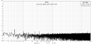
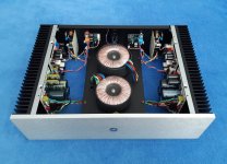
A "traditionally" wired amplifier can also be quiet. I give my KLA120 as an example. The attached pictures explain the wiring diagram and measurements.
-94 dBV = 20 uVrms


-94 dBV = 20 uVrms
Attachments


Last edited:
That's a good result. The SLB's are breaking any ground ground loops and keeping the amplifiers floating. There's no doubt a good dual mono bloc can be quieter than a standard single PSU stereo amp.
I won't get into an argument on this, I but your HF loop is still quite big.
Do you think you could get it quieter if the second toroid had a GOSS band?
Did you rotate you transformers a bit to find the null noise point?
Anyway, an excellent result!
I won't get into an argument on this, I but your HF loop is still quite big.
Do you think you could get it quieter if the second toroid had a GOSS band?
Did you rotate you transformers a bit to find the null noise point?
Anyway, an excellent result!
Don't these HF loops operate in three dimensional space simultaneously too?
(Just wondering idly whilst brandishing a pointed stick).
(Just wondering idly whilst brandishing a pointed stick).
Yes - the field radiates spherically out from a current carrying conductor. However, the 2D depictions we use here are good enough to explain the fundamentals or wiring up for low noise.
The transformers are not big, only 170VA, I did not try to rotate them (look at the picture, you will understand why 🙂 ).
Both channels have very low (approx -120dBV level) mains related spectrum components at idle. The goss band does the job, important to shield that transformer which is closer to the inputs/outputs/amp_pcb. If the distance is more than 10cm the effect is negligible. Regarding HF noise I do not understand what you meant.
-94dBV is the total integrated noise and hum in the audio band (20-22k unweighted).
Attachments
You might be able to rotate the transformers just a few degrees - sometimes that’s a enough to make a difference. You would have to monitor the output on the sound card.
HF would be diode turn off ringing on the main bridge rectifies - but looking at your build, I assume you would have taken good care of that 😀.
Very nice build!
HF would be diode turn off ringing on the main bridge rectifies - but looking at your build, I assume you would have taken good care of that 😀.
Very nice build!
Hi Bonsai and all,
I hope you can help me understand this observation. I have a dual mono PS feeding 2 channels. The torroid I'm using is a dual 18-0-18 100VA each winding.
I do not yet have the center tap (0V) from the PS transformer connected to safety earth (and the chassis) yet. When I measured the AC voltage between the center tap and the chassis it read around 65V. BTW, the safety earth and chassis are connected.
I noticed a lot of hum when I connected the amp to a test speaker. I then connected the center tap (0V) to the chassis, and the hum reduced significantly. This test was performed with the inputs shorted at the amp.
1. Why is there 65V AC at the center taps?
2. Why is there a hum reduction when there are no interconnects from/to the amp under test?
My plan is to implement the ground lifters for both the channels.
Thanks
G.O.S.S. band initially stood for: "Grain Oriented Silicon Steel" band. This is a well known alloy but in this particular instance its' name has been used to name what it really is: a steel screen. Nothing more and nothing less.
Now, look carefully to the image below, previously shown in this conversation. It indicates that MU metal screen can be even more effective. So, there is an optional solution here.

Now, look carefully to the image below, previously shown in this conversation. It indicates that MU metal screen can be even more effective. So, there is an optional solution here.
Please can you make a drawing. I am very surprised you have 65 V between the centre tap and 0V.Hi Bonsai and all,
I hope you can help me understand this observation. I have a dual mono PS feeding 2 channels. The torroid I'm using is a dual 18-0-18 100VA each winding.
I do not yet have the center tap (0V) from the PS transformer connected to safety earth (and the chassis) yet. When I measured the AC voltage between the center tap and the chassis it read around 65V. BTW, the safety earth and chassis are connected.
I noticed a lot of hum when I connected the amp to a test speaker. I then connected the center tap (0V) to the chassis, and the hum reduced significantly. This test was performed with the inputs shorted at the amp.
1. Why is there 65V AC at the center taps?
2. Why is there a hum reduction when there are no interconnects from/to the amp under test?
My plan is to implement the ground lifters for both the channels.
Thanks
Hi Bonsai and all,
I hope you can help me understand this observation. I have a dual mono PS feeding 2 channels. The torroid I'm using is a dual 18-0-18 100VA each winding.
I do not yet have the center tap (0V) from the PS transformer connected to safety earth (and the chassis) yet. When I measured the AC voltage between the center tap and the chassis it read around 65V. BTW, the safety earth and chassis are connected.
I noticed a lot of hum when I connected the amp to a test speaker. I then connected the center tap (0V) to the chassis, and the hum reduced significantly. This test was performed with the inputs shorted at the amp.
1. Why is there 65V AC at the center taps?
2. Why is there a hum reduction when there are no interconnects from/to the amp under test?
My plan is to implement the ground lifters for both the channels.
Thanks
Have you checked for earth fault in your house?
Thank you stinius. I tested the extension strip for a earth leakage test using a multimeter from: https://www.wikihow.com/Check-Earthing-at-Home
I got these results in V AC:
L -> N : 247
L -> E : 9
E -> N : 0
The results were wrong for L -> E, so I suspected the extension strip to be broken, which had some electronics to detect fault conditions. I realised that the fault detection on the strip was not functional at all.
I then replaced the strip with a simpler one, and performed the same tests, and measured L -> N as 247.
I will remeasure the center tap to chassis AC voltage after this change and report back.
I measured the AC voltage from the center tap to the chassis, and I still get 65-78 VAC. I get this reading in a different amp as well. Both amps do not have the center tap (0V) connected to the chassis (safety earth) using the GLB yet. Any cause for concern?Thank you stinius. I tested the extension strip for a earth leakage test using a multimeter from: https://www.wikihow.com/Check-Earthing-at-Home
I got these results in V AC:
L -> N : 247
L -> E : 9
E -> N : 0
The results were wrong for L -> E, so I suspected the extension strip to be broken, which had some electronics to detect fault conditions. I realised that the fault detection on the strip was not functional at all.
I then replaced the strip with a simpler one, and performed the same tests, and measured L -> N as 247.
I will remeasure the center tap to chassis AC voltage after this change and report back.
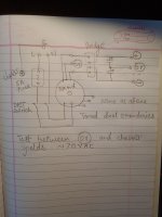
Please can you make a drawing. I am very surprised you have 65 V between the centre tap and 0V.
As Bonsai requested, information is needed. In addition to a schematic of your power supply, pictures that clearly show the power supply and wiring would also be helpful.
Please find attached the simplified PS schematicAs Bonsai requested, information is needed. In addition to a schematic of your power supply, pictures that clearly show the power supply and wiring would also be helpful.
Attachments
Here's a good example of a dual mono commercial amp which takes an alternative approach to grounding (and decoupling). It's worth noting:
- A separate power 0V star between the main power caps for each channel
- A 0V signal star located on the LHS of the board, with a skinny connection to the power OV stars
- No local decoupling
- Speaker 0V returns go to the respective power star (not the local on board 0V like Bonsai's amps)
- Case in earthed, but the circuit is floating (which is very common for commercial amps)
This works well in practice. There's more that one way to skin a cat and some produce better sound than others.
- Home
- Amplifiers
- Solid State
- Wiring Up Dual Mono Amplifier