Good evening, please bare with me on this as I’m a bit wet behind the ears when it comes to Amplifiers,
This eve I changed the bulbs in the VU meters to LED’s as the old ones had blown. My problem is when I turned it back on to test it there was a little pop sound and the magic smoke was released from the left channel amp board!
I took out the power amp board and I think I found the culprit, a fried resistor. But when I went to check the service manual to find the value it isn’t on the schematic so I removed the other channel to visually check and this resistor is not even present?
upon further inspection the transistors on the affected channel have been changed to 2SD555 and 2SB600 before I owned the amp as opposed to the original ones 2SD665 and 2SB645.
I downloaded the service manual for the 170DC and the resistor R731 is on the schematic as shown. What part does this resistor play? Did the tech make a mistake by putting it in or is it there to adjust for the different transistors??
Any help would be greatly appreciated
thanks
Matt
Attachments

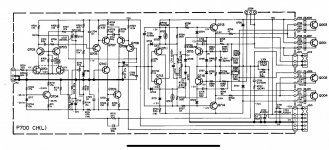
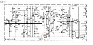
I will add that the corresponding resistor on the positive rail is not present either?Good evening, please bare with me on this as I’m a bit wet behind the ears when it comes to Amplifiers,
This eve I changed the bulbs in the VU meters to LED’s as the old ones had blown. My problem is when I turned it back on to test it there was a little pop sound and the magic smoke was released from the left channel amp board!
I took out the power amp board and I think I found the culprit, a fried resistor. But when I went to check the service manual to find the value it isn’t on the schematic so I removed the other channel to visually check and this resistor is not even present?
upon further inspection the transistors on the affected channel have been changed to 2SD555 and 2SB600 before I owned the amp as opposed to the original ones 2SD665 and 2SB645.
I downloaded the service manual for the 170DC and the resistor R731 is on the schematic as shown. What part does this resistor play? Did the tech make a mistake by putting it in or is it there to adjust for the different transistors??
Any help would be greatly appreciated
thanks
Matt
Does the unit appear original inside, if so then assume there are errors in the service manual. Service manuals are often not updated with changes made during production. I would only add/remove components after careful analysis, the fact that a components is missing/included in the service manual is not reason enough, again assuming the item is still original, all bets off if someone has tinkered with it.
https://audiokarma.org/forums/index.php?threads/marantz-170dc-p700-amp-board-pcb-replica.926613/a little confusing,
"According to the pdf's I have, there is no power supply P800 board in 170dc model. That's why they don't use the 2 last pins on J702 (P700) if it is 170dc model and R730,R731 should not be soldered-in if the P700 PCB is used for 300dc... "
Point is, don't rush and possibly make things worse, do some more research...
I would think that a Service Supplement (if available) would be the wise thing to check before going further.
https://audiokarma.org/forums/index.php?threads/marantz-170dc-p700-amp-board-pcb-replica.926613/a little confusing,
"According to the pdf's I have, there is no power supply P800 board in 170dc model. That's why they don't use the 2 last pins on J702 (P700) if it is 170dc model and R730,R731 should not be soldered-in if the P700 PCB is used for 300dc... "
Point is, don't rush and possibly make things worse, do some more research...
No, the transistors on the problem channel have been replaced at some point over 20 odd years ago. The transistors only on the affected channel, (left), have been changed from 2SD665 and 2SB645 to 2SD555 and 2SB600. The right channel I’m assuming and as far as I can tell is original. At this point I’m guessing this extra resistor was added because of the different transistors, the resistor is only on the negative side. The opposing resistor R730 on the positive rail was left absent?Does the unit appear original inside, if so then assume there are errors in the service manual. Service manuals are often not updated with changes made during production. I would only add/remove components after careful analysis, the fact that a components is missing/included in the service manual is not reason enough, again assuming the item is still original, all bets off if someone has tinkered with it.
That’s what I have spotted too, it shouldn’t be present on the 300DC. As mentioned I can only assume it was added along with the addition of different output transistors??https://audiokarma.org/forums/index.php?threads/marantz-170dc-p700-amp-board-pcb-replica.926613/a little confusing,
"According to the pdf's I have, there is no power supply P800 board in 170dc model. That's why they don't use the 2 last pins on J702 (P700) if it is 170dc model and R730,R731 should not be soldered-in if the P700 PCB is used for 300dc... "
Point is, don't rush and possibly make things worse, do some more research...
As far as I can see there is only one service manual online and I have it. 👍I would think that a Service Supplement (if available) would be the wise thing to check before going further.
Does anyone else have any idea why the resistor may of been added into R731 only? I’m completely stuck without a reason for it being there or any ideas on the value. With all the unobtainium this on the board it’s not something I’m comfortable trying to replace or even omit for fear of blowing any or all of the transistors the the board.
the AK posting suggests that the 170DC and 300DC share the same board and that R731 is only applicable to the 170DC possibly due to (external) cabling options/unused pins...
That is what I’m starting to think, so what has that resistor been doing for the last 20 odd years that I’ve owned it and god know how long before then it was inserted? Lolthe AK posting suggests that the 170DC and 300DC share the same board and that R731 is only applicable to the 170DC possibly due to (external) cabling options/unused pins...
AK postings = prone to BS and biased claims and information.
Original Mfr documents = less BS to deal with.
Don't listen to those "online" self-made experts.
Original Mfr documents = less BS to deal with.
Don't listen to those "online" self-made experts.
- Home
- Amplifiers
- Solid State
- Marantz 300DC power amp problem