First - Happy New Year 🙂
For more than a year now I'm more or less working on this project. Now I thought it was time to share everything with you. So depending on how you like it - here are all the files for you. (Next Post)
It is a Broadband Driver Unity-Horn - I call them the "SB-Horn V3" (Sub-Broadband-Horn Version 3)
HF & MF consist of a 2" full range driver. At the moment it is the NE65W-04 Sometimes I find the sound of the NE65 a bit "metallic". Therefore tests with the Tymphany TC6FD00-04, which has a paper membrane, will follow. As LF the horn is "loaded" with two 6.5" Dayton Audio DCS165-4 in BR configuration.
BR Tuned to 35Hz.

Sound familiar? Yes - I found this one on the net a year ago & thought, surely this can be "reshaped" -> https://quint-store.com/h-a-v-o-f-a-s-t-fun
So I searched until I thought I had found the right horn. Then I have the contour Abgeformt & completely redesigned. The print time per half-WG is about 20h with a 0.8mm Nozzle (Creality CR-10 Max).
This is the Waveguide: PRV Audio WG45-50 2" 90 x 40 ABS
Here you can see how I molded & re-constructed as Unity:


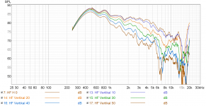
RAW-HF response 0 to 50 deg horizontal (gated @4.1ms due to Room issues):

Since it is extremely difficult for me to measure properly at home below 500hz. Many series of measurements later I had "a feel" for what the speaker does. So please be a little merciful with me 🙂
What I did - compared between the gated measurents, the near field measurement and the ground plane. If you then look at Vituix predicted cross-over & compare with the smoothed near-field measurement - have I made exrem nonsense here?
By the way - if the input-mearuement data for vituix is gated at a certain point, vituix seems to interpolate in a way:


Here are all the measurements:


.png")
.png")


ATTENTION: Unfortunately both of my boxes have a huge problem! Check out the impedance measurement of the LF. At pretty much 180Hz, my 3D print resonates pretty strongly. I printed my horns with 100% infill. Nevertheless, this resonance occurs there. At high volumes, this is then unfortunately strongly audible, at low volumes not.
My guess - as soon as the woofers are screwed to the 3D print, the screws "pull up" a few 3D print layers. These then resonate with each other - which is exactly how it sounds. A friend who rebuilt my horns for his bachelor thesis does not have this problem. So it is probably "only" due to my print.
I recommend: Instead of screwing the woofers - glue pins into the holes of the 3D print. Then "lash" the woofers against each other.
For more than a year now I'm more or less working on this project. Now I thought it was time to share everything with you. So depending on how you like it - here are all the files for you. (Next Post)
It is a Broadband Driver Unity-Horn - I call them the "SB-Horn V3" (Sub-Broadband-Horn Version 3)
HF & MF consist of a 2" full range driver. At the moment it is the NE65W-04 Sometimes I find the sound of the NE65 a bit "metallic". Therefore tests with the Tymphany TC6FD00-04, which has a paper membrane, will follow. As LF the horn is "loaded" with two 6.5" Dayton Audio DCS165-4 in BR configuration.
BR Tuned to 35Hz.
Sound familiar? Yes - I found this one on the net a year ago & thought, surely this can be "reshaped" -> https://quint-store.com/h-a-v-o-f-a-s-t-fun
So I searched until I thought I had found the right horn. Then I have the contour Abgeformt & completely redesigned. The print time per half-WG is about 20h with a 0.8mm Nozzle (Creality CR-10 Max).
This is the Waveguide: PRV Audio WG45-50 2" 90 x 40 ABS
Here you can see how I molded & re-constructed as Unity:
RAW-HF response 0 to 50 deg horizontal (gated @4.1ms due to Room issues):
Since it is extremely difficult for me to measure properly at home below 500hz. Many series of measurements later I had "a feel" for what the speaker does. So please be a little merciful with me 🙂
What I did - compared between the gated measurents, the near field measurement and the ground plane. If you then look at Vituix predicted cross-over & compare with the smoothed near-field measurement - have I made exrem nonsense here?
By the way - if the input-mearuement data for vituix is gated at a certain point, vituix seems to interpolate in a way:
Here are all the measurements:
ATTENTION: Unfortunately both of my boxes have a huge problem! Check out the impedance measurement of the LF. At pretty much 180Hz, my 3D print resonates pretty strongly. I printed my horns with 100% infill. Nevertheless, this resonance occurs there. At high volumes, this is then unfortunately strongly audible, at low volumes not.
My guess - as soon as the woofers are screwed to the 3D print, the screws "pull up" a few 3D print layers. These then resonate with each other - which is exactly how it sounds. A friend who rebuilt my horns for his bachelor thesis does not have this problem. So it is probably "only" due to my print.
I recommend: Instead of screwing the woofers - glue pins into the holes of the 3D print. Then "lash" the woofers against each other.
Attachments

Here are all files for you to download:
https://www.dropbox.com/sh/77jlhlbv1m5bcnf/AADxa761kjfXdCrUzKuUmPOZa?dl=0

...if someone would like to, then I can also add the LF phase plugs into the STL of the WG, so that only once would have to be printed. I have pasted mine afterwards, because I have designed them only while the first print was running 🙂

..reminds me of this 😀:

OK - feel free to rebuild, work on it & let's philosophize about it
Best regards from Leipzig, Christian 😊
https://www.dropbox.com/sh/77jlhlbv1m5bcnf/AADxa761kjfXdCrUzKuUmPOZa?dl=0
...if someone would like to, then I can also add the LF phase plugs into the STL of the WG, so that only once would have to be printed. I have pasted mine afterwards, because I have designed them only while the first print was running 🙂
..reminds me of this 😀:
OK - feel free to rebuild, work on it & let's philosophize about it
Best regards from Leipzig, Christian 😊
The horn is screwed to the housing from outside. The horn is inserted into the back housing via a "Z-slot". This creates a nice clean transition.
..Afterwards, I thought it would have been nice to make the horn in front really round. Unfortunately, this idea came too late. But maybe someone of you does that. Maybe I'll make a STL for it sometime.
Like this:

More Pictures:


..Afterwards, I thought it would have been nice to make the horn in front really round. Unfortunately, this idea came too late. But maybe someone of you does that. Maybe I'll make a STL for it sometime.
Like this:
More Pictures:
These heat set insert nuts work really well for 3D prints, you put a soldering iron in the nut wait for it to heat up and then push it into the plastic to the depth you want. You should be able to use them with your print and see if it solves the problem.My guess - as soon as the woofers are screwed to the 3D print, the screws "pull up" a few 3D print layers. These then resonate with each other - which is exactly how it sounds. A friend who rebuilt my horns for his bachelor thesis does not have this problem. So it is probably "only" due to my print.
https://www.aliexpress.com/store/gr...5968.html?spm=a2g0o.detail.0.0.535f5a54jvzciu

I've come across this before, but for whatever reason I didn't dare to order any. Maybe I thought I can have it easy....
Then I'll probably have to order some.
Then I'll probably have to order some.
Forgetting that I had still done that. "Adapter" for the original PRV horn, if someone wants to rework that. Just glue the extension on the PRV and then mill the ports.
..But have not tried it myself yet whether it fits, so it is a bit experimental. Maybe I'll print one tonight and see if it fits.
Files are:
SB-Horn V3 - PRV-Horn Extension - ALL
SB-Horn V3 - PRV-Horn Extension
SB-Horn V3 - PRV-Horn Extension - Ring 8mm
(...& the Phase Plug File...)

..But have not tried it myself yet whether it fits, so it is a bit experimental. Maybe I'll print one tonight and see if it fits.
Files are:
SB-Horn V3 - PRV-Horn Extension - ALL
SB-Horn V3 - PRV-Horn Extension
SB-Horn V3 - PRV-Horn Extension - Ring 8mm
(...& the Phase Plug File...)
- Home
- Loudspeakers
- Multi-Way
- Broadband-Driver Unity Horn // "SB-Horn V3"