Hi,
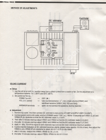
I'm trying to do the idling current adjustment on a Denon PMA-560 (steps in attachment).
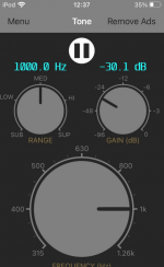
In one step it needs a 1 kHz, 10 mV RMS signal to be applied. Would it be ok to use an iPhone app for this
("audio signal generator"), or am I better off buying a dedicated signal generator?
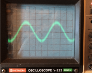
Also attached a screenshot of the audio signal generator app, and the output of an old scope on that signal
(voltage divider set to 10 mV).
thanks 🙂
happy 2022 🙂
I'm trying to do the idling current adjustment on a Denon PMA-560 (steps in attachment).
In one step it needs a 1 kHz, 10 mV RMS signal to be applied. Would it be ok to use an iPhone app for this
("audio signal generator"), or am I better off buying a dedicated signal generator?
Also attached a screenshot of the audio signal generator app, and the output of an old scope on that signal
(voltage divider set to 10 mV).
thanks 🙂
happy 2022 🙂
Attachments
is this due to the unit being repaired?
the signal appears quite noisy or the scope isn't properly focused, but if it's all you have then go with it.
the signal appears quite noisy or the scope isn't properly focused, but if it's all you have then go with it.
It's because of this issue:
https://www.diyaudio.com/community/threads/denon-pma-560-major-overhaul.374007/#post-6893554
No idea if the two are related, to be honest.
Karl did the adjustment, but he didn't have a signal source, so he couldn't do those steps (5-8).
https://www.diyaudio.com/community/threads/denon-pma-560-major-overhaul.374007/#post-6893554
No idea if the two are related, to be honest.
Karl did the adjustment, but he didn't have a signal source, so he couldn't do those steps (5-8).
so this is an attempt to resolve an intermittent fault with the output relay, i've had a cursory read of the thread but it seems that other than cleaning and tweaking no components where replaced correct?
No, the output relay tripping was on my PMA-560, which was eventually fixed by cleaning the speaker selector.
The confusion is probably because this involves two amplifiers:
Karl bought his own PMA-560 and did that major overhaul, I then bought it from him.
I really like it, except for those bright highs. So I'm now trying to figure out how to tweak that.
My guess would be that the many capacitor changes changed the frequency response.
I'm trying to do this idle current adjustment with the 1 kHz signal, only because Karl didn't do it yet
(from my limited knowledge I'd think that this doesn't influence the frequency response).
the idle current adjust is for thermal stability and if the amp is not exhibiting excess heating leave well enough alone.
if it seems bright there is tone controls....or maybe the tweaking you need to be doing should be with your speakers say in the form of an L Pad on the tweeters or mids. i venture your amp and speaker choice that sounded good to you previously now seems bright indeed because of cap replacements and the overly bright speakers compensated for an amp that overtime had developed a weak high end response.
if it seems bright there is tone controls....or maybe the tweaking you need to be doing should be with your speakers say in the form of an L Pad on the tweeters or mids. i venture your amp and speaker choice that sounded good to you previously now seems bright indeed because of cap replacements and the overly bright speakers compensated for an amp that overtime had developed a weak high end response.
Thanks for the info 👍
I now replaced the stock power cord with the one that was on my old amp: a shielded cable, grounded to the chassis, and with a ferrite core around it where the cable enters the amp (see picture).
This seems to improve things (still some more listening to do 🙂

I now replaced the stock power cord with the one that was on my old amp: a shielded cable, grounded to the chassis, and with a ferrite core around it where the cable enters the amp (see picture).
This seems to improve things (still some more listening to do 🙂
With a 'scope the noise bandwidth is often vast (100MHz or more), so noise amplitude can be deceptively high as you are getting mainly RF noise contributing to the trace. There might also be some bleed-through of the iPhone's DAC clocking frequency in there too, pick up from switching power supplies, etc.the signal appears quite noisy or the scope isn't properly focused
And with a 10x probe you have about 400nV/√Hz Johnson noise across the lower portion of the audio spectrum anyway from the 9M series resistor in the probe.
My 'scope shows a lot of 1/f noise with the input shorted (and a small hump around 15--20kHz too oddly enough), not surprizing as broadband DC coupled amplifiers have a lot of conflicting design pressures to consider, principally flat frequency response and group-delay, and 1/f noise isn't a primary concern.
Basically a 'scope isn't a good tool to characterize noise, let alone audio noise.
With a 'scope the noise bandwidth is often vast (100MHz or more), so noise amplitude can be deceptively high as you are getting mainly RF noise contributing to the trace. There might also be some bleed-through of the iPhone's DAC clocking frequency in there too, pick up from switching power supplies, etc.
Thanks for the info. I got curious and tried a few more things:
- measuring in a different room, far away from (computer) equipment
- measuring iPad instead of iPod
- using a shorter audio cable (basically a jack + a 1cm cable)
- using different probes
- switching iPod to airplane mode
the iPod output set to zero (scope squares still at 10 mV x 10 mV, focus is ok,
the line of "GND" is nice and sharp).
So so far I've only established what isn't the cause 🙂
I now replaced the stock power cord with the one that was on my old amp: a shielded cable, grounded to the chassis, and with a ferrite core around it where the cable enters the amp (see picture).
Ok, I'm an idiot, it's not a shielded cable (pretty clear from that picture as well..).
Time to dig up info on the benefits of using an actual shielded power cable.. 🙄
What happens if you short the 'scope probe to ground? I suspect the noise will still be there, as its from the 'scope and its probe.
Forgive my ignorance, but how do I set this up?What happens if you short the 'scope probe to ground? I suspect the noise will still be there, as its from the 'scope and its probe.
(I'm thinking shorting to ground would trivially always get the flat line on the scope?)
Here's a picture of my measuring setup:
lose the clip lead, that should reduce the noise being picked up.
and grounding the input is as simple as putting the switch adjacent the probe connector to the "gnd" position (then if i'm not mistaken the focus is is second one down next to the screen (adjust for finest trace) i'd also reduce the intensity to just over cutoff to give a visible trace)
and grounding the input is as simple as putting the switch adjacent the probe connector to the "gnd" position (then if i'm not mistaken the focus is is second one down next to the screen (adjust for finest trace) i'd also reduce the intensity to just over cutoff to give a visible trace)
Last edited:
have you looked at your signal now?
in post 14 it's a little hard to see, but it looks like you've attached the scope gnd (flying lead off the probe) to the signal lead and vice versa.
in post 14 it's a little hard to see, but it looks like you've attached the scope gnd (flying lead off the probe) to the signal lead and vice versa.
Last edited:
say what...?Basically a 'scope isn't a good tool to characterize noise, let alone audio noise.
I looked at the signal without the red connector wire (i.e. attached the signal lead to the probe directly),have you looked at your signal now?
no real difference in the output there.
in post 14 it's a little hard to see, but it looks like you've attached the scope gnd (flying lead off the probe) to the signal lead and vice versa.
Sorry, it is hard to see, here's a closeup (so it is ground to ground):
- Home
- Amplifiers
- Solid State
- using an iphone app for a calibration signal?