Hello all,
may I introduce my newest build:
A power amplifier, only with TO39 metal can transistors (-> this project on my own page, in german)
Some month ago I got a large amount of old unused electronic parts.
Including many transistors in TO39 housing: BC140, BC160, BSX45; also many electrolytic capacitors of larger capacity: 4700uf etc ..
Too good to throw away, so what can you do with it?
I got the idea to build an amplifier with it and only use these TO39 transistors, even for the output devices.
Some might think that's nonsense, but it doesn't matter: here the thing is and it works.
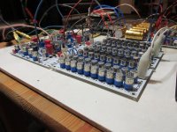
After countless LTSpice simulation runs, I finally made the PCB layouts and had the boards made.
Since you always order several boards, I designed the layouts in such a way that the remaining boards could also be used for "normal" amplifiers, e.g. with TO126 and TO264, SOT-93 or similar transistors. For this reason, the TO39 output transistors sit on their own circuit board.
The capacitors in the parts convolut were all axial, so the power supply board has space for axial and radial smoothing capacitors.

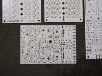
The power supply is regulated and offers a stable voltage of + 20V and -20V.
More is not possible for the amplifier, since the transistors BC140 / BC160 can only withstand 40V.
The supply contains an electronic fuse which switches off the operating voltage of the amplifier if a set current value is exceeded.
There is also an interface that enables the power supply unit to be shut down with an external switching voltage; this is e.g. used by the DC-Protection.
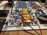
The output transistors are sitting quite close together and have no heat sinks; with convection only they don't get rid of their heat, so a fan is required. Here, however, a very low air flow is sufficient, so that no annoyingly loud, powerful fan is necessary.
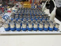
So the amplifier can continuously deliver 30 watts into 4 ohms (per channel) without unhealthy heating.
If someone misses the obligatory small coil at the output: it will later be on the DC protection board; but at the moment the Amp works without it, no problems.
Everything is fitted onto a PVC plate for the function test. The next goal is to make a suitable housing. And, consequently, to replace the SOT-93 series transistors in the power supply unit with the extra board with TO39 transistors.
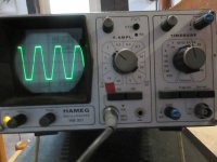
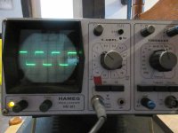
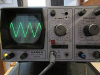
Here are some more photos and oscillograms.
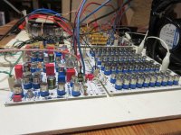

output board assembly:
the resistors for the output transistors are fitted to the downside of the board.
after every new fitted transistor was tested, if they all work as one
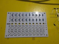
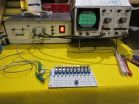
(There are 7 PNPs, 8 NPNs on the main board, 20 PNP / NPNs each on the output board, a total of 55 transistors, per channel)
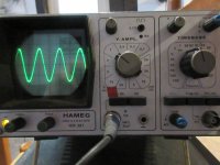
sinus 1000 Hz .......................sinus clipping 1000 Hz............rectangle 1000 Hz..................triangle 10000 Hz
(each with probe head 10:1)
-> this project on my own page, in german
may I introduce my newest build:
A power amplifier, only with TO39 metal can transistors (-> this project on my own page, in german)
Some month ago I got a large amount of old unused electronic parts.
Including many transistors in TO39 housing: BC140, BC160, BSX45; also many electrolytic capacitors of larger capacity: 4700uf etc ..
Too good to throw away, so what can you do with it?
I got the idea to build an amplifier with it and only use these TO39 transistors, even for the output devices.
Some might think that's nonsense, but it doesn't matter: here the thing is and it works.

After countless LTSpice simulation runs, I finally made the PCB layouts and had the boards made.
Since you always order several boards, I designed the layouts in such a way that the remaining boards could also be used for "normal" amplifiers, e.g. with TO126 and TO264, SOT-93 or similar transistors. For this reason, the TO39 output transistors sit on their own circuit board.
The capacitors in the parts convolut were all axial, so the power supply board has space for axial and radial smoothing capacitors.


The power supply is regulated and offers a stable voltage of + 20V and -20V.
More is not possible for the amplifier, since the transistors BC140 / BC160 can only withstand 40V.
The supply contains an electronic fuse which switches off the operating voltage of the amplifier if a set current value is exceeded.
There is also an interface that enables the power supply unit to be shut down with an external switching voltage; this is e.g. used by the DC-Protection.

The output transistors are sitting quite close together and have no heat sinks; with convection only they don't get rid of their heat, so a fan is required. Here, however, a very low air flow is sufficient, so that no annoyingly loud, powerful fan is necessary.

So the amplifier can continuously deliver 30 watts into 4 ohms (per channel) without unhealthy heating.
If someone misses the obligatory small coil at the output: it will later be on the DC protection board; but at the moment the Amp works without it, no problems.
Everything is fitted onto a PVC plate for the function test. The next goal is to make a suitable housing. And, consequently, to replace the SOT-93 series transistors in the power supply unit with the extra board with TO39 transistors.
Here are some more photos and oscillograms.


output board assembly:
the resistors for the output transistors are fitted to the downside of the board.
after every new fitted transistor was tested, if they all work as one


(There are 7 PNPs, 8 NPNs on the main board, 20 PNP / NPNs each on the output board, a total of 55 transistors, per channel)
sinus 1000 Hz .......................sinus clipping 1000 Hz............rectangle 1000 Hz..................triangle 10000 Hz
(each with probe head 10:1)


-> this project on my own page, in german
Last edited:
Hi, one of the coolest amp builds I have ever seen. Almost makes we wish a had a bucket of TO39s, almost. Congratulations on a really unique build.
not really... even so...there are ways to go around that.Base capacitance must be huge.
Hi....
I think, I should show the circuit, but it's standard, nothing special.
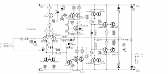
This is, what can be on the main Board. The above shown output devices (BD249/250) here are placeholders.
Instead of them (T16,T18) and their Emitter-Resistors(RT16/RT18), is connected the 40 output transistor board, shown below.
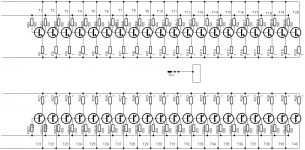
If someone wants to play around with it, I add the LTSpice file.
greetings
Markus
I think, I should show the circuit, but it's standard, nothing special.

This is, what can be on the main Board. The above shown output devices (BD249/250) here are placeholders.
Instead of them (T16,T18) and their Emitter-Resistors(RT16/RT18), is connected the 40 output transistor board, shown below.

If someone wants to play around with it, I add the LTSpice file.
greetings
Markus
Attachments
BTW:
These BC140/160 have ft=50Mhz.
Siemens datasheet says: collector base capacitance < 25pF (BC140), < 30pF (BC160).
Even with many paralleled not so bad, compared to the e.g. often used
SA1943 Cob=360pF, SC5200 Cob=200pF
These BC140/160 have ft=50Mhz.
Siemens datasheet says: collector base capacitance < 25pF (BC140), < 30pF (BC160).
Even with many paralleled not so bad, compared to the e.g. often used
SA1943 Cob=360pF, SC5200 Cob=200pF
I have to concur. Unconventional ideas, turning into real projects, like this one need to be admired!
Best regards!
Best regards!
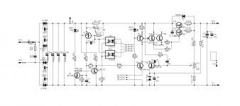
The power supply should not be forgotten to mention in more detail.
The built-in electronic fuse saved me from smoke signals more than once during testing the amplifier, when I was inadvertently producing short circuits when attaching alligator clips or with shaky test probes... or if something was overshot when testing the clipping limit...
The fuse is quite quick; with a complete short circuit with a breaking current of e.g. 8A current still flows for approx. 80μs. You can practically hold the connections together, the shutdown happens so quickly that you hardly see a spark.
There is a power supply board for each rail voltage. The boards are connected via the interfaces (optocoupler) mentioned above. If the fuse responds in only one voltage, the other voltage is also switched off so that the amplifier is not connected to only one rail.
below the circuit for one rail:

Very Nice
I agree, unconventional designs deserve admiration.
And all together just fun.
Many people find older tech like tubes to be inspirational.
For some reason I find T0-39 and T0-3 metal packages
Very interesting for a listen and looking at.
Music is Art, might as well make the Amplifier Art as well
I agree, unconventional designs deserve admiration.
And all together just fun.
Many people find older tech like tubes to be inspirational.
For some reason I find T0-39 and T0-3 metal packages
Very interesting for a listen and looking at.
Music is Art, might as well make the Amplifier Art as well
Excellent idea yours ... For NPN given my large availability I will use 2N3019 ... I am looking for suitable PNP ... Among the available ... The aim is to use the available material ...
It is also my aim to use what is available first, if possible.I am looking for suitable PNP
for PNP-Types you could possibly use: 2N4030...4033, 2N2905 (?), if you have them in your parts box
I can't tell you for sure. I can only look at the data sheets, which you have probably already done. After that I would say yes, it should work.
I like this very much!
Also a like the Beast of 1000 jFETs.
I have several bucket loads of can transistors I could use for this.
Maybe BC440/441 and BC460/461? I probably have 20 pairs of those...
Also a like the Beast of 1000 jFETs.
I have several bucket loads of can transistors I could use for this.
Maybe BC440/441 and BC460/461? I probably have 20 pairs of those...
- Home
- Amplifiers
- Solid State
- The TO39-AMP (40 Output Transistor Fun Project)