Hi All.
A neighbours friend came over recently with a pair of TDL Electronics RTL3 Loudspeakers which he donated to me.
How could I say no?
Externally they're in reasonable condition but missing the material which goes over the square ports at the bottom front of the boxes.
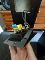
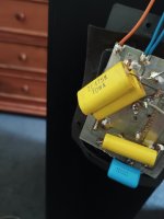
I pulled out the rear terminal plate/crossovers to find yellow poly caps fitted to one of the crossovers, but no additions on the other.
If anything the crossover which hadn't been upgraded appears to have missing parts.
I'm thinking, rather than try to work out whats been done and what's faulty or missing, I might try building crossovers from scratch.
These can be a mixture of existing parts with addition of new parts.
I'll need a crossover schematic but haven't had any luck tracking one down.
Any link or access to the crossover schematics would be very much appreciated.
Cheers Cliff
A neighbours friend came over recently with a pair of TDL Electronics RTL3 Loudspeakers which he donated to me.
How could I say no?
Externally they're in reasonable condition but missing the material which goes over the square ports at the bottom front of the boxes.
I pulled out the rear terminal plate/crossovers to find yellow poly caps fitted to one of the crossovers, but no additions on the other.
If anything the crossover which hadn't been upgraded appears to have missing parts.
I'm thinking, rather than try to work out whats been done and what's faulty or missing, I might try building crossovers from scratch.
These can be a mixture of existing parts with addition of new parts.
I'll need a crossover schematic but haven't had any luck tracking one down.
Any link or access to the crossover schematics would be very much appreciated.
Cheers Cliff
Attachments
Last edited:
Rebuild, with original filter & values provided:
https://vikash.info/audio/mtm_floorstander/crossover_measurements.aspInteresting that, according to our friend Vikash, who used to be active here, they're another one who used a resistive shunt on the midbass units. Assuming the drivers are wired in series (probable), then according to Vikash's averaged driver measurements, that should put impedance for that leg at about 6.8ohms, nominal, and probably helped damp it down in the LF too, giving a bit more of that nominal TL effect. For them to work as intended / designed, you'll need some open-cell foam to go in the terminus.
https://vikash.info/audio/mtm_floorstander/crossover_measurements.aspInteresting that, according to our friend Vikash, who used to be active here, they're another one who used a resistive shunt on the midbass units. Assuming the drivers are wired in series (probable), then according to Vikash's averaged driver measurements, that should put impedance for that leg at about 6.8ohms, nominal, and probably helped damp it down in the LF too, giving a bit more of that nominal TL effect. For them to work as intended / designed, you'll need some open-cell foam to go in the terminus.
Last edited:
wel, 5 min google gave me this:

https://vikash.info/audio/mtm_floorstander/crossover_measurements.asp
https://vikash.info/audio/mtm_floorstander/crossover_measurements.asp
Yes, per my link above. Assuming the impedance hasn't shifted significantly, the extra padding he added on the tweeter is likely a good move if it was running with excessive gain in the original, as implied.
Thanks guys.
Being a novice at schematic conventions, just need clarification regarding the diagrams.
The dots (points) either side of the Source. Are these positive and negative Loudspeaker input terminals?
Where "+" appears next to the woofer, shouldn't these terminals be + & -?
Also, do I parallel the woofer terminals to both woofers?
Where "-" appears next to the tweeter, shouldn't these terminals be + & -?
The RP1 & RP2 section. Are LPads available which include these values or do you add your selected resistors to a variable circuit?
Sorry for the dumb questions.
Cliff
Is extra padding a good way of toning down tweeters which tend to be too sharp?Yes, per my link above. Assuming the impedance hasn't shifted significantly, the extra padding he added on the tweeter is likely a good move if it was running with excessive gain in the original, as implied.
Yes, if they're simply running at a higher level than that of the LF unit -not uncommon in commercial practice at the time these were built as they needed to do things like this to make them stand out in a showroom. If it's an issue with their inherent response, then it may require additional changes. Judging from Vikash's measurements though, it worked out fine.
Thanks guys.
Being a novice at schematic conventions, just need clarification regarding the diagrams.
The dots (points) either side of the Source. Are these positive and negative Loudspeaker input terminals?
Yes. Electrically speaking it actually means the output terminals of the amplifier, but since the RTL3 has biwiring terminals on the back, if you're not used to circuit schematics it's probably easier to view it as meaning the speaker's own terminals.
No, it's just denoting that the woofer is wired in positive electrical polarity, the tweeter in reversed electrical polarity.Where "+" appears next to the woofer, shouldn't these terminals be + & -?
Only if that's how they are currently wired.Also, do I parallel the woofer terminals to both woofers?
Where "-" appears next to the tweeter, shouldn't these terminals be + & -?
See above; it's just denoting that the tweeter is wired in reversed electrical polarity, i.e. the nominal positive input is attached to the negative tweeter terminal & visa versa.
Just buy two resistors (for each speaker): a 1ohm and a 10ohm. For safety, I'd suggest they're rated as 10w at least. You'd probably be fine with 5w, but these are not expensive components, especially if you stick with regular white ceramic wire-wound types, so I can't see much point on using smaller types, unless you've physically no room.The RP1 & RP2 section. Are LPads available which include these values or do you add your selected resistors to a variable circuit?
Sorry for the dumb questions.
They're not dumb if you don't know the answer or where to look. 😉
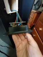
Confirming the woofers are in parallel.
Both woofer terminals soldered to brown (+), and blue wires.
The tweeters are soldered to orange and green wires but there doesn't appear to be any markings on the tweeters to denote which terminal is the -ve.
I'll be building the new crossovers around the existing wiring, but I might need to know which of the orange and green is the -ve?
Only if that's how they are currently wired.
Rather than guessing, get hold of an ordinary 9v battery, or even an AA at a pinch. Attach one wire to the + battery terminal, and one to the - battery terminal. If the dome moves out, the wire attached to the + terminal is the +, and visa versa. This is usually easier to see on larger drivers, but you should have sufficient movement even with a tweeter to establish which is which.
At the crossroads now.
The current crossovers boards are too small for replacement parts and a bit of a rats nest.
For me the best option is to create new boards/layout.
One option is to completely replace everything with poly caps, by pass caps, air core inductors, & good resistors for an outlay of $131 plus shipping.
I can reduce my costs by:
Keeping the existing iron core inductors.
Use regular white ceramic wire-wound resistors which I have on hand.
Drop the by pass caps.
I had a poor experience with regular white ceramic wire-wound resistors when attempting to adjust a pair of speakers.
I had tried various values but the result was to muffle electric guitar when playing tracks.
I had excellent results when playing around with by pass caps a pair of Yamaha vintage speakers.
Am I over capitalizing?
Will improvement be noticeable using air core over iron core?
Are the bypass caps at $16 the pair be worthwhile trying?
Also the existing Inductor values are 243 uH & 633 uH.
The closest I can find to these are 0.22mH / 0.25mH & 0.62mH / 0.65mH.
Which values would you recommend, and do I choose 15awg or 18awg?
thanks
Very much a case of 'whatever you feel like' because you'll never (ever) get a great deal of consensus on this subject.
- Resistors = whatever you feel like, is in budget, fits and is electrically speaking in the desired spec. The shunt over the midbass units is likely best as a wirewound given the power-handling & heat dissipation etc., and make very sure it's of at least the same wattage rating as the existing. If you want to over-spec. the rating for that one -no harm in doing so.
- Re the inductors, it's impossible to know in advance. I prefer air cores as a rule, providing the DCR is where you need it (use the 0.25mH and 0.65mH in whichever gauge puts DCR nearest the current inductors to avoid altering the XO transfer functions if you do change), but with those speakers, I'd be surprised if you got significant gains.
- No way of knowing re the bypass caps. Depends if they do anything at all (a long way from being a given and controversial to say the least), what the caps themselves are, and whether you like what they do, assuming they do something audible. If you want something cheaper, try to find a polystyrene or MKP from a big component supplier in the desired value. JBL used to use 0.01uF MKP and a 0.005uF polystyrene shunting their main caps. Cost pennies.
Last edited:
Does that discount MOX?Very much a case of 'whatever you feel like' because you'll never (ever) get a great deal of consensus on this subject.
- Resistors = whatever you feel like, is in budget, fits and is electrically speaking in the desired spec. The shunt over the midbass units is likely best as a wirewound given the power-handling & heat dissipation etc., and make very sure it's of at least the same wattage rating as the existing. If you want to over-spec. the rating for that one -no harm in doing so.
I was thinking of Jantzen 10 watt Superes wire wound resistors.
Do you think this is overkill for this project?
I had positive experience on another project with Cornell Dubilier 940C / 0.01uF @ $8 each.No way of knowing re the bypass caps. Depends if they do anything at all (a long way from being a given and controversial to say the least), what the caps themselves are, and whether you like what they do, assuming they do something audible. If you want something cheaper, try to find a polystyrene or MKP from a big component supplier in the desired value. JBL used to use 0.01uF MKP and a 0.005uF polystyrene shunting their main caps. Cost pennies.
The only specs I could get for the replacement air core inductors was:
- Re the inductors, it's impossible to know in advance. I prefer air cores as a rule, providing the DCR is where you need it (use the 0.25mH and 0.65mH in whichever gauge puts DCR nearest the current inductors to avoid altering the XO transfer functions if you do change), but with those speakers, I'd be surprised if you got significant gains.
For the 0.25uH version: 0.128Ω for 15awg, 0.22Ω for 18awg, & 0.4Ω for 21awg
For the 0.65uH version: 0.24Ω for 15awg, 0.38Ω for 18awg, & 0.8Ω for 21awg
Does that help to select correct awg?
Also, do you think the quality of these speakers isn't good enough to be able to reproduce improvements made by upgrading Inductors?
Measure the resistance of the original coils first to know their DCR figures. Also use the zeroing button (delta) on the DMM to subtract the test leads resistance.
They could read out highish due to thin wire despite they are aided for less turns by their cores. That would have been augmenting the bass drivers Q. But also creating losses. Sometimes it helps to halve those figures in new coils because they were simply compromises, sometimes they were expertly blended into the original alignment.
A friend had those back in the mid 90's and I remember them natural enough sounding for the most part. Also with more extended and less resonant bass than conventionally ported rival speakers in their price range and era. They worth some better crossover components IMHO. Mainly to aid midrange resolution because I remember them a bit dark there. Midway 18awg for both coils should be safe. Place those chokes away from each other and in right angles. Also clean the binding posts very well with Deoxit or alike.
Thanks Salas.A friend had those back in the mid 90's and I remember them natural enough sounding for the most part. Also with more extended and less resonant bass than conventionally ported rival speakers in their price range and era. They worth some better crossover components IMHO. Mainly to aid midrange resolution because I remember them a bit dark there. Midway 18awg for both coils should be safe. Place those chokes away from each other and in right angles. Also clean the binding posts very well with Deoxit or alike.
How does Deoxit compare to brightening posts with 0000 grade steel wool?
Does not scratch the metal and adds some lubricating protection film to battle future oxidization. Both solutions readily remove oxides with steel wool even more aggressively so. Can of Deoxit is general use for all kind of electrical contacts and its good to have around if fixing stuff. Especialy to spray inside switches you can not reach without removal and disassembly. For an one off accessible job maybe not worth it because it is expensive. WD-40 could also work on brass posts. But never spray it in potentiometers.
I have CRC 2.26Does not scratch the metal and adds some lubricating protection film to battle future oxidization. Both solutions readily remove oxides with steel wool even more aggressively so. Can of Deoxit is general use for all kind of electrical contacts and its good to have around if fixing stuff. Especialy to spray inside switches you can not reach without removal and disassembly. For an one off accessible job maybe not worth it because it is expensive. WD-40 could also work on brass posts. But never spray it in potentiometers.
Do you think it would perform a similar role?
I use it to recondition potentiometers.
- Home
- Loudspeakers
- Multi-Way
- TDL Electronics RTL3 Loudspeakers advice!