Do you have a DXT (H1499) lying around?
Yes, I do. As I understand, it is best suited for narrow or wide baffles and xo maybe at 2k. I might try anyway. I hope to avoid the plaster thing 😱
After having massaged various profiles, cabinets sizes, damping values, etc. in AKABAK I have gotten to the point where the general profile of the directivity is following along the same lines as the published Dutch 8C. I am not seeing the same level of attenuation in simulation, but given this is a simulation that does not surprise me either.
While I do not have any sort of quantifiable equation, a few rules of thumb appear to be emerging...
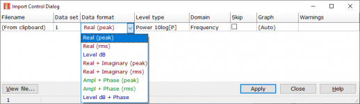
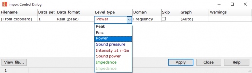
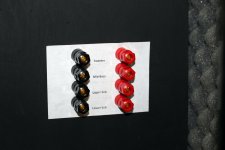
Next step would be to try and more accurately simulate the damping material in AKABAK. They do have a "curve object" that lets you apply a curve to various parameters, including the wall impedance. I did find a large repository of sound absorption coefficients here. However, I am not up to snuff on the math and if those are directly transferable into AKABAK. Options for import are attached. If anyone has any suggestions on which is correct or what manipulation is required to make one of them correct, that would be great!
While I do not have any sort of quantifiable equation, a few rules of thumb appear to be emerging...
- The smaller the enclosure, the more touchy the port and associated parameters get. I seemed to have better luck with a smaller squarish hole than the long rectangular profile at smaller volumes.
- The internal blocking around the port is critical for adjusting delay between the front of the speaker and the sides.
- The internal blocking and the damping material seem fairly reliant on one another. By adjusting one or the other I could get either smooth even attenuation across the 100-500hz territory, or I could get higher attenuation at a smaller range while getting something vaguely more dipole-ish in the rest of the range. Dutch 8C shows something similar albeit higher between 500-1Khz
Next step would be to try and more accurately simulate the damping material in AKABAK. They do have a "curve object" that lets you apply a curve to various parameters, including the wall impedance. I did find a large repository of sound absorption coefficients here. However, I am not up to snuff on the math and if those are directly transferable into AKABAK. Options for import are attached. If anyone has any suggestions on which is correct or what manipulation is required to make one of them correct, that would be great!
Attachments

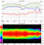
For reference, attached are two outputs from the same model, only difference is the damping values. Can see how one trades higher attenuation for less extension down towards and more dipole-ish response above. The other is smoother and reaches lower but has less max attenuation.
Attachments


Great AKABAK stuff. I did install AKABAK, but it is a steep learning curve. Woodwork is faster for me🙂 What volume do you use for the simulation? My volume is now about 6 liters.
I tried to reduce the tweeter DI by cutting off about 3mm of the throat. It went in the right direction, but a new XO is required.
I tried to reduce the tweeter DI by cutting off about 3mm of the throat. It went in the right direction, but a new XO is required.
Attachments
Nice work guys, keep on going 🙂
pbanshee,
Is this the same thing as above? Do you mean with damping the absorption coefficients of some material or something else?
Thanks!🙂
pbanshee,
Could you tell more about this, what damping you adjust and which direction, more or less? The port attenuation or back side in general, how this would relate to a real world prototype?The internal blocking and the damping material seem fairly reliant on one another. By adjusting one or the other I could get either smooth even attenuation across the 100-500hz territory, or I could get higher attenuation at a smaller range while getting something vaguely more dipole-ish in the rest of the range. Dutch 8C shows something similar albeit higher between 500-1Khz
For reference, attached are two outputs from the same model, only difference is the damping values. Can see how one trades higher attenuation for less extension down towards and more dipole-ish response above. The other is smoother and reaches lower but has less max attenuation.
Is this the same thing as above? Do you mean with damping the absorption coefficients of some material or something else?
Thanks!🙂
Great AKABAK stuff. I did install AKABAK, but it is a steep learning curve. Woodwork is faster for me🙂 What volume do you use for the simulation? My volume is now about 6 liters.
Went a little overboard playing with scale (while maintaining driver size) and it is currently sitting around 21 liters. I have older versions at various scales that I want to go back and manipulate some more now that I am getting a better grip on the parameters that I make meaningful difference.
Could you tell more about this, what damping you adjust and which direction, more or less? The port attenuation or back side in general, how this would relate to a real world prototype?
Is this the same thing as above? Do you mean with damping the absorption coefficients of some material or something else?
Correct same thing. All damping I have tested so far as been strictly inside the port. I have been using the generalized damping model built-in to AKABAK so it is not necessarily true to real life damping material; just a starting point. By adjusting the damping frequency in AKABAK it should be similar to changing an IRL damping material. I have experimented a bit with the damping material shape/dimensions/thickness, but have mostly kept it to around 30mm thick. That said, I did notice that smaller boxes seemed need most of the damping in the center of the port, and less at the edges. Haven't fully confirmed that though.
What this seems to indicate is there are trade offs for using ultra dense highly absorbent materials vs say maybe one that is slightly less absorbent. If I can figure out a way to apply sound absorption coefficients in AKABAK then I should be able to get closer what more or less ideal materials may be for a given cabinet.
Yeah this is what I found in the emulation as well, you don't want any attenuation in the absorption material for good cancellation so thin / less absorbing works better in this regard. The other aspect of the material as part of "the delay system", where the box size and port size, box width and port location also affects.
Basically the (constant) delay on the backwave was all we needed to form a cardioidish pattern. When attenuation to the backwave is introduced, the cancellation is less because the sound from front is louder in comparison. The pattern gets varying shapes when the delay and/or attenuation is frequency dependent.
Please post if you do more findings, AKABAK seems powerful software. Thanks!🙂
Last edited:
Core of all this is the damping material. If no suitable one is found, one could perhaps "tune" the damping material with compression. In general, less is better, thin acoustic materials should yield better response than heavy insulation.
Good point. A couple of weeks ago I built the third prototype enclosure and so far I have satisfactory results but lack the time to come to a conclusion as I'm building a speaker measurement turntable to use with Clio. I concocted a mechanism that can apply variable pressure on the damping material without the need to open the enclosure. If you know which factors affect the delay you can compensate the response to your desire.


To Dave123: It's not easy to get the cardioid to work really well. There are a few DIY people and companies who have tried, but nobody seems to get results better than a wide-band rejection of approximately 10 dB relative to the front. That's what I got as well in my first few designs. I've since figured out a repeatable method to achieve between 15 and 20 dB. Inside I still feel like the DIY nerd I was ten years ago, and therefore I feel this urge to share all my 'secrets'. But my partners would be very angry with me if I did.
Some general pointers (some of which have been raised by others as well): the depth of the enclosure matters a lot; the kind of material has an influence (rockwool, fiberglass, polyester wool all work well); it generally helps to have the slots relatively close to the front baffle.
Here you'll find a photo of the inside of the 8c's cabinet: 6moons: audioreviews Dutch & Dutch 8c
The Olympus' cardioid works better than most I've seen, but only after I replaced the perforated back-panel with a solid panel: 2-way: Waveguide + Cardioid-like
If you feel the 8c doesn't play loud enough, I can highly recommend the 12" mid format with multi-sub!
Sorry, I just saw your input after some months. I appreciate your concern and willingness to help others, despite the fact that you are running a business, and it would be a better idea to keep the secrets under wraps.

Good point. A couple of weeks ago I built the third prototype enclosure and so far I have satisfactory results but lack the time to come to a conclusion as I'm building a speaker measurement turntable to use with Clio. I concocted a mechanism that can apply variable pressure on the damping material without the need to open the enclosure. If you know which factors affect the delay you can compensate the response to your desire.
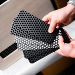
Interresting with the adjustable damping. I have looked into a lot of images and it seems d&d also have tried different MF grilles. There is a big difference in the air opening between these two. Looks like the one with less opening is used now.
I made the Arta turntable some years ago. It is running fully automatic and it is fast to make the measurements.
Paal
Attachments

Tried to make a 0-180deg measurement. It is indoor and only about 4mS of IR. The port seems to work well in the 200-600Hz area.

Looks like you even have -12dB at 100hz which is nothing to sneeze at. What material were you using, how thick, and was it compressed?
It is 5cm of fibreglass. No compression. I also have a little syntetic wool behind the magnet to stabilize the stuffing. The big difference seems to be in port size. The port is about 200 x 58mm, but the plate I use reduces the open area with more than 50%
Looks good! is this for the 8c type enclosure you posted few months ago? Difference to my enclosure is that the outer dimensions are quite different, I wonder how much that affects the response.Tried to make a 0-180deg measurement. It is indoor and only about 4mS of IR. The port seems to work well in the 200-600Hz area.View attachment 1005895
Hi tmuikku,Looks good! is this for the 8c type enclosure you posted few months ago? Difference to my enclosure is that the outer dimensions are quite different, I wonder how much that affects the response.
Thanks. Yes it is the last cab I posted. Looks much like 8c cab. In the beginning, it was without the mesh in the port. With the mesh, it is more like a semi open cab.
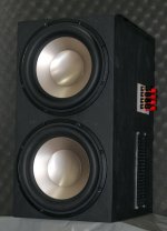
After getting good result on a sole midbass driver in a passive resistive cardioid, it's time to integrate it into a complete speaker. The idea is pretty the same as 8c. Two 10" boundary coupled bass drivers at the rear side (from Seas), eight inch midbass (also from Seas) and TPL-150H (from Beyma). The cabinet is made of 8mm Birch pkywood and the cardioid chamber is made of 36mm Birch plywood to stiffen whole enclosure. I may change the 8" and the tweeter if needed. I applied a precolor in black, it's a prototype and will be eliminated when I'm done.


These ten inch Seas drivers deserve an above-heavyweight league, delicately! The speaker weights about 35kg/77lbs. I'm gonna use four channels of Hypex Ncore amps and miniDSP 4x10HD. Hypex DLCP is also at hand.
Attachments


In a diy way maybe this could do the trick https://www.robinetterie-hammel.fr/outillage/tampon-abrasif-pour-nettoyage-tube-cuivre-32498.htmlor any extra fine triple zero grade steel wool for wood furniture cleaning.
An abrasive Tampon would have quite a different translation in English 😱In a diy way maybe this could do the trick https://www.robinetterie-hammel.fr/outillage/tampon-abrasif-pour-nettoyage-tube-cuivre-32498.htmlor any extra fine triple zero grade steel wool for wood furniture cleaning.
- Home
- Loudspeakers
- Multi-Way
- Resistive port cardioid active speaker insipired by D&D 8C