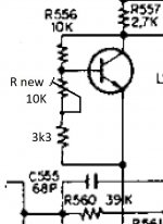
Use a 5k pot between R555 and R556, with the wiper to the base of the transistor.Is there a way to add a bias control that isn't too complicated? Here's a schematic.
Last edited:
Use a 5k pot between R555 and R556, with the wiper to the base of the transistor.
One must design the circuit in such a way that if one day the potentiometer goes bad-ish or just dirty (the moving wiper does not make good contact during adjustment even if it is just for a brief moment) the current through the power transistors will go low, not high.
Is there a way to add a bias control that isn't too complicated?
Replace R555 with a 10k potentiometer in series with a 3.3k or a 4.7k resistor, see attached schematic
Attachments
Last edited:
Yes, R555 is the place to modify the bias. But if, as you say, the bias is too low with 5.6K then that should be the upper limit, but it can't be far off so I would recommend 3k3 fixed and a 2.5K pot.
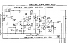
NB, be sure R565 and R566 1.5 Ohm resistors are not open. That could be your problem. Note this "diodes on the emitter resistors circuit" is a poor attempt to avoid thermal runaway that I would not recommend. When I was in the business, years ago, we had a huge amp that did this and I would clip the diodes, which reduced the output slightly but made the amp much more reliable. The best solution is more heat sink and smaller emitter resistors, but then there are other improvements this old amp needs so let's leave it at that.
NB, be sure R565 and R566 1.5 Ohm resistors are not open. That could be your problem. Note this "diodes on the emitter resistors circuit" is a poor attempt to avoid thermal runaway that I would not recommend. When I was in the business, years ago, we had a huge amp that did this and I would clip the diodes, which reduced the output slightly but made the amp much more reliable. The best solution is more heat sink and smaller emitter resistors, but then there are other improvements this old amp needs so let's leave it at that.
What parts are different?I've rebuilt one channel of this amp but the bias is now too low because of the different parts. Is there a way to add a bias control that isn't too complicated? Here's a schematic.
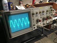
Well I implemented the bias adjustment and that works well, but it is still doing the thing. Here is a picture on the scope.
It definitely seems like the amp is not getting along with different outputs because if I move the new outputs to the good channel the problem moves too. I tried clipping those diodes but no change.
When the sound hits a certain level it distorts and the sinewave shakes back and forth. I probably need to change a ceramic cap value?
Attachments
Replaced a few other transistors, but the issue moves to the other channel when I move only the new output transistors. So it is the circuit not liking the new outputs. I tried a couple different part #s tooWhat parts are different?
That scope trace looks like instabilities in the quasi side of the output. This is not unreasonable with replacement transistors. The first thing to try is replace C559 with 100nF aka 0.1uF, and consider moving it to the other side of C558, the big electrolytic. If that doesn't clean up the output, then increase the compensation cap C552 to as much as 47pF.
Changed C559 to 0.1uf and tried it on both sides of the output cap. That didn't have much impact.That scope trace looks like instabilities in the quasi side of the output. This is not unreasonable with replacement transistors. The first thing to try is replace C559 with 100nF aka 0.1uF, and consider moving it to the other side of C558, the big electrolytic. If that doesn't clean up the output, then increase the compensation cap C552 to as much as 47pF.
Upping C552 to 44pF didn't have any effect, and the original cap said 39 on it. Was that 39pF maybe? The schematic is actually for a slightly different model but appeared to be the same. Was the only schematic I could find.
Upping that cap to 220pF fixed the problem. Didn't have any values in between handy. There's probably something around here somewhere though.
Ya, that would be 39pF. 220p is a bit large, but 100p is typical. Be sure R563 and R564 (470 Ohm) are not open. This happens when the outputs blow. 470 is a bit high and 100 Ohms is typical in this position, and might also help your instabilities, but it's harder on the driver transistors. Bigger amps use as small as 47 Ohms, but they have larger driver transistors. Try lifting C555 (68p) or adding 1k in series with it, although that could just make things worse. Adding 10nF across R561 (100) may help. Some might suggest shorting R561 but it's there to protect the VAS transistor (Q506?).
What would be the consequence of that cap being too large?Ya, that would be 39pF. 220p is a bit large, but 100p is typical. Be sure R563 and R564 (470 Ohm) are not open. This happens when the outputs blow. 470 is a bit high and 100 Ohms is typical in this position, and might also help your instabilities, but it's harder on the driver transistors. Bigger amps use as small as 47 Ohms, but they have larger driver transistors. Try lifting C555 (68p) or adding 1k in series with it, although that could just make things worse. Adding 10nF across R561 (100) may help. Some might suggest shorting R561 but it's there to protect the VAS transistor (Q506?).
Both channels looked good to full power at 1kHz.
This thing doesn't have to be totally perfect, it is a not high end unit for a client that doesn't want to spend a ton on it. Sounds like it is not the best designed amp.
The channel I'm tuning is the previously good channel with the new outputs in it. So there's definitely no other damage causing the issue. The channel that was blown has the outputs from the good side, and the rest of the transistors are new. It is working well with no other adjustments.
A large compensation capacitor causes slew limiting, ie the current from Q504 and R553 is limited so the rate at which the compensation cap voltage changes is limited. You may be able to see this at 20KHz, but not likely at 1KHz. This is the root cause of so-called TIM (transient intermodulation distortion) which makes the sound kinda mushy. Ya, in your situation, it may be best to quit while you are ahead. Given unlimited time and patients, there is a long list of "upgrades" you could do, but your client may be happiest to get it back working asap.
- Home
- Amplifiers
- Solid State
- Sony HP-610a add bias adjustment?