They are silent on low efficiency speakers . Get more efficient speakers and they all hum. Audio Note is not known for really quiet operation. I also made that phono stage and it is humming nicely😁 Making a really quiet tube circuit is not that easy .
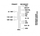
Hoping this is a simple question from a first timer to all you smart folks: I have the same kit, I'm about to wire up the transformer to the M2 power supply. Original kit instructions say to connect one 300 plus one 0 transformer taps to ground, one 0 to one of the 300V inputs on the board, and the remaining 300V transformer tap to the other 300V input on the board. However, My transformer, the Hammond 272BX has only 300-0-300 (plus the other voltages. How can I make this work? See attached pictures. Many thanks!!!
Attachments

Hoping this is a simple question from a first timer to all you smart folks: I have the same kit, I'm about to wire up the transformer to the M2 power supply. Original kit instructions say to connect one 300 plus one 0 transformer taps to ground, one 0 to one of the 300V inputs on the board, and the remaining 300V transformer tap to the other 300V input on the board. However, My transformer, the Hammond 272BX has only 300-0-300 (plus the other voltages. How can I make this work? See attached pictures. Many thanks!!!
Another quick one, I hope: I've checked my components several times. PS V-out by the voltage regulator chips says it should be 6v2. I'm getting 12.6 V between + and -. Also, 0V between - and ground and 12.3V between + and ground. Is this correct? One schematic (attached) I've seen for this PS says +12V. Before I connect the phono amp board, wanted to reach out. Thanks!!

I may have gotten a partial answer by diving into the data sheets. The 12AX7, if the heaters are in series (one lead on pin 4, one on pin 5) should have 12.6V across them, so that works out. The 6922 data sheet, on the other hand asks for 6.3V +-0.6 on pins 4 to 5. The board I have has one heater V supply to 4 and 5 together and the other on pin 9. So, a mystery to me.
More information, this is a board purchased from AliExpress by my father that he asked me to build up for him.
Sale page on AliExpress
Below is my photo of the underside of the board below V1, the 6922. Here is why I hesitate to apply power to this board:
Data sheet says that pins 4 and 5 are for the 6.3V heater circuit, and pin 9 is the "internal shield", see Link to data sheet
However, this board instructs me to put heater V to pins 9 and 5 (with pin 4 shorted to pin 5 on the PCB)
If this is horribly wrong, as I suspect, I suppose I can
- desolder the mount leg for pin 5, shield it as it goes through the hole in the PCB then solder the other heater V supply line directly to it (yay...McGuyver).
- Redo the part of the supply circuit for this valve's heater to actually give 6.3 V, for that, I will also need advice. Is is regulated by an L78S05 (see sale page again for the top view of this circuit. R15 of the power supply board is labeled 1k-2.7k and currently has a 2.7k. Perhaps that can be changed out to give the more acceptable value.
Finally I was able to eliminate the hum, I used a different ground plane and used an inductor instead of the gyrator or the resistor and everything was well silenced. Now I did some tests with another transformer I had aside, a double C-Core and I noticed that it lowers the background noise a little more, but the transformer is a 320-0-320 instead of 300-0 -300. By mounting it, everything works perfectly and the output voltage is correct, I was wondering if it was appropriate to lower these total 40v, perhaps by increasing the first resistance from 100ohm, or given the correct output voltage to leave everything unchanged?
Connect the power supply to pins 4 and 5 and feed only the filaments and see if they light up correctly, there must have been an error on the description. For the heater circuit replace the regulator and add the diodes on the board, the voltage should already be good.More information, this is a board purchased from AliExpress by my father that he asked me to build up for him.
Sale page on AliExpress
Below is my photo of the underside of the board below V1, the 6922. Here is why I hesitate to apply power to this board:
Data sheet says that pins 4 and 5 are for the 6.3V heater circuit, and pin 9 is the "internal shield", see Link to data sheet
However, this board instructs me to put heater V to pins 9 and 5 (with pin 4 shorted to pin 5 on the PCB)
If this is horribly wrong, as I suspect, I suppose I can
- desolder the mount leg for pin 5, shield it as it goes through the hole in the PCB then solder the other heater V supply line directly to it (yay...McGuyver).
- Redo the part of the supply circuit for this valve's heater to actually give 6.3 V, for that, I will also need advice. Is is regulated by an L78S05 (see sale page again for the top view of this circuit. R15 of the power supply board is labeled 1k-2.7k and currently has a 2.7k. Perhaps that can be changed out to give the more acceptable value.
View attachment 1009567
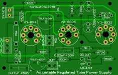
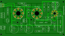
2 years ago, I decided to design my own Audio Note power supply because I thought it would be very interesting having an adjustable regulated tube PS for my tube preamps. As I had no ECL82, i replaced it with a pentode (6SJ7) and a single triode(6C4). It work fine so far. Here comes the question. Would I had to replace the cathode and plate resistors and capacitors because of the new tubes? In a new design I have drawn with sprint 6.0 I use 6X4, 6005 and 8532 which I have in a big stock. Do you think is going to work with the existing Audio Note configuration? Thanks a lot for any answers and suggestions in advance.
Attachments
Member
Joined 2009
Paid Member
This raises questions for me. I would assume the regulator performance perfectly good enough to lower the HT ripple without the need for a choke before it. So it should be fine with a resistor. And if not, the gyrator should have been a suitable replacement for the choke.Finally I was able to eliminate the hum, I used a different ground plane and used an inductor instead of the gyrator or the resistor and everything was well silenced. Now I did some tests with another transformer I had aside, a double C-Core and I noticed that it lowers the background noise a little more, but the transformer is a 320-0-320 instead of 300-0 -300. By mounting it, everything works perfectly and the output voltage is correct, I was wondering if it was appropriate to lower these total 40v, perhaps by increasing the first resistance from 100ohm, or given the correct output voltage to leave everything unchanged?
You made several changes, do you know if the “different” ground plane was enough to fix the problem?
- Home
- Source & Line
- Analog Line Level
- Audio note kit l3 phono