I've laid out a couple of PCBs from schematics I found on the Elliott Sound Products page (https://sound-au.com/) for single-sided home etching.
I've tried various Op amps from the 5532, LM4562, and OPA2134... I like the resolution of the LM4562, however, this op amp turns my circuits into a radio! I get bleeps and bloops from god knows what, probably WIFI and nearby computers, and whatever electronics my neighbors are running.
From what I have read - the LM4562 can be sensitive to things like PCB layout. Admittedly, I have never considered interference issues with much of the PCBs i've laid out until now.
I usually make it a game of trying to make the most compact layout with the least number of jumpers, I'm guessing this approach doesn't work well for super sensitive devices like the LM4562...
Would any of you be able to look at my layouts and tell me what I'm doing wrong with the output stage and phono preamp layouts below to give me such interference problems? And why the tone control circuit is somehow more quiet despite using the same op amps?
I could just use one of the other op amps... but I would like to know what the fundamental issues are.
Thanks in advance!
Ironically, the least noisy layout is the one I like the least... So I fear this is something that's counterintuitive to me that's going to be where I hit the "Wall" as an electronics hobbyist 🙁
I'd go to a double sided board, with a solid ground plane on the top side.
All ground leads go directly to the ground plane. Each IC supply terminal
should be bypassed directly to the ground plane right at the pin.
No sockets and SO-8 package are better. Also need the pcbs in a fully shielded enclosure.
All ground leads go directly to the ground plane. Each IC supply terminal
should be bypassed directly to the ground plane right at the pin.
No sockets and SO-8 package are better. Also need the pcbs in a fully shielded enclosure.
Last edited:
This is one of the downsides of the otherwise excellent LM4562 - its very sensitive to RF(*), so you have to keep RF out of your enclosure - a feedthrough capacitor on the input might be one strategy, although they aren't easy to come by, but some CG0 input capacitance to ground right on the connector is second-best, although there's a limit to how much you can add in a MM cartridge input, depending on the cable capacitance.
And a metal enclosure is mandatory anyway because of mains capacitive pickup, just make sure all the connectors are screened I guess, and add ferrite toroid over the input cables close to the case.
However the LM4562 isn't a great choice for a MM phono amp, its got relatively large amounts of current noise, an NE5532/5534 will outperform it for noise and be rather less RF sensitive. Any low voltage-noise FET input opamp is well worth considering too, things like the OPA165x family for instance, very low current noise, much less sensitive to RF.
(*) https://www.audiosciencereview.com/...pecially-of-the-lm4562-lme497x0-family.10687/
https://gearspace.com/board/showpost.php?p=12990908&postcount=17
Just add a 100 ohm resistor in series with the IC’s non inverting input, assuming you are using that for signal input.
Ironically, the least noisy layout is the one I like the least... So I fear this is something that's counterintuitive to me that's going to be where I hit the "Wall" as an electronics hobbyist
Indeed...
https://www.diyaudio.com/community/...see-its-stable-havent-you.191389/post-2616266
Would you know it was unstable by listening ? Well actually, you may not, and may put the change in sound down to the op-amp ! The AD797 certainly sounded over bright and thin but I can imagine some saying, "hey listen to that extra detail" it just shows how murky and dull the 5534 was. A bit extreme maybe, but you see my point.
Mark makes some good points on the LM4562 and they are very valid but I have to counter that and say that I've actually found them pretty docile to work with.
Your output stage or SE to balanced stage may be oscillating. Add some capacitance to the feedback loops (e.g. 33pF)
Capacitors like C7 and C12 should not be connected directly to the inverting input. Capacitors make good antennas.
I had this problem with other op amps too and it was always a layout issue. Swapping the capacitor's position with its series resistor fixed it.
"add a 100 ohm resistor in series with the IC’s non inverting input" This might work.
I had this problem with other op amps too and it was always a layout issue. Swapping the capacitor's position with its series resistor fixed it.
"add a 100 ohm resistor in series with the IC’s non inverting input" This might work.
I went through some similar concerns with replacing opamps with lm4562's.
Here's the thread (it not too long)
I substituted some opamps, now I'm nervous
Here's the thread (it not too long)
I substituted some opamps, now I'm nervous
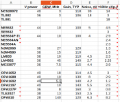
I measured a noise level this morning, to compare some IC accumulated in stock for a few years.
Circuit is simplest, G = 10^4, negative feedback 100 k, both inputs to ground 10 oHm.
What I noticed,, on o-scope screen, LM4562 has periodic (10 Hz) spikes, my guess is some kind of auto-zero offset correction is running in the background.
There is only one OP TLE2027 has similar behaviour but much smaller in magnitude.
BTW, to my surprise NJM2068 outperform almost all IC in collection, except OPA227
Attachments
I'm also dealing with LM4562 noise in an MM phono amp. It's the Rod Elliott ESP P06. The unit is relatively quiet with the LM833.
As I already replied earlier in this thread the noise may be due to oscillations. LM4562 can be considered a high-speed op amp so it may require some capacitance in the feedback loop.
There is no auto-zero in the LM4562.I measured a noise level this morning, to compare some IC accumulated in stock for a few years.
Circuit is simplest, G = 10^4, negative feedback 100 k, both inputs to ground 10 oHm.
What I noticed,, on o-scope screen, LM4562 has periodic (10 Hz) spikes, my guess is some kind of auto-zero offset correction is running in the background.
There is only one OP TLE2027 has similar behaviour but much smaller in magnitude.
BTW, to my surprise NJM2068 outperform almost all IC in collection, except OPA227
If you measure 10 Hz spikes, my guess is that you have a Wi-Fi router or something similar in the vicinity. The LM4562 is very "good" at detecting RF signals.
Shielding the circuit and decoupling to ground (if a good ground plane is available) will most likely be needed.
I think i’m going to give up on the LM4562 until I decide to send this circuit to the board house with a double-sided layout with a ground plane. Because self-etching a 2-sided board is annoying :/
Voltage noise of the LM4562 is normally good (some samples have bad 1/f noise though), but for a MM phono amp this is irrelevant as the large current noise of the LM4562 makes it a poor performer for this application (cartridge inductance is huge). The NE5534A is 4 times better for current noise, and any JFET opamp thousands of times better. The LM833 is similar to the 5534A in noise performance, which is why its quieter than the LM4562 for this application.I'm also dealing with LM4562 noise in an MM phono amp. It's the Rod Elliott ESP P06. The unit is relatively quiet with the LM833.
None of the shown circuits have the meanwhile mandatory RC input filter (well, it was here already standard decades ago). It explains part of the issues. LM4562 can perform OK but it might be a good idea to use standard design techniques if only to prevent issues. If you use relatively fast/high bandwidth parts then don't be surprised the circuits pick up HF/RF and do nice things with that.
HF/RF is all around us by our own wish and it creeps in everywhere. This is somewhat counterproductive when choosing fast parts for audio 😀 So protect your audio circuits with simple standard methods.
Tip: adding a microrelay and a handful of parts shorting outputs to GND at power on/off is a cheap and nice enhancement. Adding the pads costs nothing, adding the relay is then still possible later on. The use of 10 µF MKT caps with 5 mm pitch for the now used electrolytic caps will give better results.
Last edited:
Its not just a question of the speed of the parts, but their actual RFI rejection, which is very poor for the LM4562 compared to most bipolar opamps even - probably the worst by a large factor.
https://www.audiosciencereview.com/...pecially-of-the-lm4562-lme497x0-family.10687/
This is a huge difference in susceptility, not a bandwidth effect as such I'd suggest. RFI rejection was not a design goal for the chip - I suspect it wasn't even considered or measured during development.
Its probably wise to specifically avoid the LM4562 when RFI is known to be a problem. If you use the LM4562 know to protect heavily against RFI (Screened enclosure and input/PSU filtering is mandatory for instance). This is easier for low-impedance circuitry as a few nF of ceramic capacitance to ground on the input is feasible to use as a an RF filter without upsetting the audio frequency response.
The specific example of a MM phono preamp is high impedance and not conducive to including a decent RF filter as the load capacitance for an
MM cartridge is crucial. This is not really an application the LM4562 would be great in, the high current noise and the EMI susceptibility are both working against you, as is the 1/f noise QC problem (you'd have to select-on-test the devices as some are good and some are bad).
However rather than jump through hoops trying to mitigate the EMI problem there's always the simple option of switching to an opamp with decent RFI rejection, such as a good JFET opamp. That sound's like a pretty good design technique in many cases 🙂
The LM4562 has superb overall performance, but two notable Achilles' heels, the 1/f noise QC issue and the RFI issue. Its hard to know if these issues will lead to it ultimately being surpassed for general purpose use though. Few devices can match its distortion performance particularly under heavy load.
If you are happy with 0.0001% distortion at 2k load and don't need 0.00003% distortion at 600 ohms, there are many competitors without those Achilles' heels out there...
I have found that LM4562s in inverting mode need both supply pins decoupled to ground, separately, right at the pins, to cure a PSU buzz. Not an issue in non-inverting mode.
High speed decoupling for an opamp often only needs to be between the two supply rails since the chip doesn't have a ground pin.
However inverting config is sort of the exception.
However inverting config is sort of the exception.
- Home
- Source & Line
- Analog Line Level
- Seeking Circuit/PCB layout advice - LM4562 Interference issue