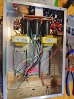
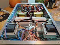
Allow me to proudly show off my newly scratch-built multi-impedance headphone amp.
It uses 12AX7 drivers and E88CC power tubes running in an SSRP configuration, driving Sowter type 8665 headphone OPTs.
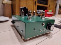
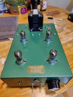
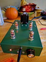
It can accommodate phones from 30-600 Ω via two selector switches on the front which I nicked off from a guitar website on switching the pick-ups (humbuckers?) from series to parallel, etc.
It sounds great with my 70Ω Sennheiser 599s with great bass and hi-end extension and has plenty of power.
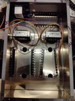
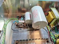
It's also dead silent, once settled down after switch-on, partly due to the oversized PS, partly due to use of Broskie's "Akido Mojo" on the SSRP power stage.
I avoided the use of electrolytics in the signal path apart from the "mojo" sub circuit which injects a portion of whatever noise remaining on B+ into the SSRP stage's cathode, thereby cancelling it's amplification (active noise reduction).
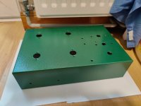
Lastly, I chose the hammered green finish as a nod to my old school's AV equipment - 16mm and filmstrip projectors all seemed to have this industrial look - hell, even the pencil sharpeners!
Very happy with my first scratch build.
It uses 12AX7 drivers and E88CC power tubes running in an SSRP configuration, driving Sowter type 8665 headphone OPTs.
It can accommodate phones from 30-600 Ω via two selector switches on the front which I nicked off from a guitar website on switching the pick-ups (humbuckers?) from series to parallel, etc.
It sounds great with my 70Ω Sennheiser 599s with great bass and hi-end extension and has plenty of power.
It's also dead silent, once settled down after switch-on, partly due to the oversized PS, partly due to use of Broskie's "Akido Mojo" on the SSRP power stage.
I avoided the use of electrolytics in the signal path apart from the "mojo" sub circuit which injects a portion of whatever noise remaining on B+ into the SSRP stage's cathode, thereby cancelling it's amplification (active noise reduction).
Lastly, I chose the hammered green finish as a nod to my old school's AV equipment - 16mm and filmstrip projectors all seemed to have this industrial look - hell, even the pencil sharpeners!
Very happy with my first scratch build.
Attachments
-
 IMG_20211206_154008.jpg577.5 KB · Views: 460
 -
 IMG_20211206_180730.jpg503.9 KB · Views: 248
 -
 IMG_20211212_091525.jpg418.9 KB · Views: 243
 -
 IMG_20211212_125438.jpg304.6 KB · Views: 252
 -
 IMG_20211213_134510.jpg398.1 KB · Views: 253
 -
 IMG_20211215_191303.jpg480.4 KB · Views: 257
 -
 IMG_20211217_183129.jpg341.8 KB · Views: 267
 -
 IMG_20211221_164336.jpg295.3 KB · Views: 255
 -
 IMG_20211223_141548.jpg356.5 KB · Views: 256
 -
 IMG_20211223_141555.jpg531.2 KB · Views: 254
 -
 IMG_20211223_153228.jpg443.9 KB · Views: 271
 -
 IMG_20211223_172943.jpg488.6 KB · Views: 288
 -
 IMG_20211221_154545.jpg416.6 KB · Views: 465
 -
 Screenshot (137).png93.7 KB · Views: 471
Very nice and neat.
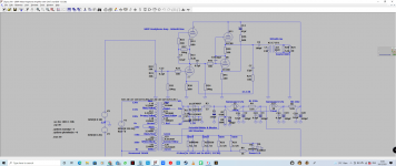
Just one thing though. I think that the maximum anode dissipation of the E88CC's is being violated. According to the datasheets this maximum is 1.5 Watt per section.
Your amplifier is drawing 19 mA per channel. The voltage after the 5K1 resistors is 230 V. So the anode to cathode voltage of one section of an E88CC is about 113 V. I don't know how much current the 12AX7 is taking but lets assume it's 2 mA (probably it's even lower). The dissipation of one section of a E88CC would than be 0.017 x 113 = 1.92 Watt, which is too much. The current through a E88CC should not be higher than 13.3 mA to stay within the limit.
I agree about the ECC88 disipation. I also use them in an SRPP configuration and because they are a true push pull you never really need more than about 6mA quiescent.
Also, what is the purpose of C16?
Cheers
Ian
Also, what is the purpose of C16?
Cheers
Ian
It defines a pole in the high frequency range and the tube amplifies this cap like an extra Miller capacitance. IMHO it is not needes, but if he wants it...
Also viewing the PSU with lots of filtering, also in my opinion, hum cancellation is not needed too.
Also viewing the PSU with lots of filtering, also in my opinion, hum cancellation is not needed too.
On the plus side, the choice of transformer is excellent. I have used the same ones in my own headphone amp designs and they are superb.
Cheers
Ian
Cheers
Ian
Strangly enough the datasheets for the ECC88/PCC88, the 6DJ8 and the EH6922 (Electro-Harmonix) give 1.8 Watt per section as maximum. But since Tubby23 writes about the E88CC and since the pictures seem to show JJ E88CC's, I based what I wrote on the Philips and JJ datasheets for the E88CC.I agree about the ECC88 disipation. I also use them in an SRPP configuration and because they are a true push pull you never really need more than about 6mA quiescent.
Also, what is the purpose of C16?
Cheers
Ian
It's meant to roll off HF beyond the audible range to curb any possibility of oscillation, similar to strapping a cap across a NFB resistor.I agree about the ECC88 disipation. I also use them in an SRPP configuration and because they are a true push pull you never really need more than about 6mA quiescent.
Also, what is the purpose of C16?
Cheers
Ian
Well, according to Merlin Blencowe, for an unbypassed optimized SSRP,Very nice and neat.
Just one thing though. I think that the maximum anode dissipation of the E88CC's is being violated. According to the datasheets this maximum is 1.5 Watt per section.
Your amplifier is drawing 19 mA per channel. The voltage after the 5K1 resistors is 230 V. So the anode to cathode voltage of one section of an E88CC is about 113 V. I don't know how much current the 12AX7 is taking but lets assume it's 2 mA (probably it's even lower). The dissipation of one section of a E88CC would than be 0.017 x 113 = 1.92 Watt, which is too much. The current through a E88CC should not be higher than 13.3 mA to stay within the limit.
RK=((2xRload)+ra)/(μ-1)
So, for my 600Ω load seen by the stage:
RK=((2x600)+(2600-1))/(33-1)
Therefore Rk must be 118Ω
I used 100Ω
Last edited:
I'll preface by saying thank you for your input and that I'm not looking for a fight - rather an understanding...OK. But the formula can't 'overrule' the maximum anode dissipation of the E88CC.
I may have this wrong but i think you're viewing max dissipation from a simple common cathode POV.
This being an SRPP - there's the interplay between the two sections...
I've searched for formulae specific to the relationship between an SRPP's loadline and Ia but can't find any.
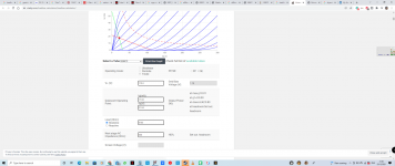
That said, I entered my values in this loadline calculator: https://www.vtadiy.com/loadline-calculators/loadline-calculator/
and it came up with these results and i don't see where its violating max dissipation.
On the contrary, the biasing point looks like its in an optimal place for the AC 600 ohm loadline rotation.
Because i cant find any specific formulae, I concluded that the equivalent anode/plate resistance to be somewhere around 5k2 per section by the two methods:
1) I short circuited my spice model by disconnecting the grid, causing Ia to rise to 22mA, then using ohms law: 113.6/0.022=5163ohm
2) I looked-up the E88CC datasheet
https://www.telefunken-elektroakustik.com/wp-content/uploads/2017/06/E88CC-TK-Tube-Data-Sheet.pdfwhich shows ra to be 2600ohm, which doubled is 5200ohm
I ran the calculator with both plate resistance values and the results were hardly any different and both within max dissipation.
Respectfully, your thoughts?
Attachments

Right there is your problem. It is not driving a 600 ohm load.Well, according to Merlin Blencowe, for an unbypassed optimized SSRP,
RK=((2xRload)+ra)/(μ-1)
So, for my 600Ω load seen by the stage:
RK=((2x600)+(2600-1))/(33-1)
Therefore Rk must be 118Ω
I used 100Ω
Cheers
Ian
But it is.Right there is your problem. It is not driving a 600 ohm load.
Cheers
Ian
The 12:1 ratio of the sowter transformer reflects 50Ω headphones into 600Ω on the primary side - that's the whole point of using them.
For my headphones specifically, for their 70Ω, the primary sees 840Ω.
I just looked at the dc-situation, so the situation without any ac-signal. The anode dissipation is given by: Pa = Ia x Va. The outcome should not violate the maximum anode dissipation as stated in the datasheets.I'll preface by saying thank you for your input and that I'm not looking for a fight - rather an understanding...
I may have this wrong but i think you're viewing max dissipation from a simple common cathode POV.
This being an SRPP - there's the interplay between the two sections...
I've searched for formulae specific to the relationship between an SRPP's loadline and Ia but can't find any.
That said, I entered my values in this loadline calculator: https://www.vtadiy.com/loadline-calculators/loadline-calculator/
and it came up with these results and i don't see where its violating max dissipation.
On the contrary, the biasing point looks like its in an optimal place for the AC 600 ohm loadline rotation.
Because i cant find any specific formulae, I concluded that the equivalent anode/plate resistance to be somewhere around 5k2 per section by the two methods:
1) I short circuited my spice model by disconnecting the grid, causing Ia to rise to 22mA, then using ohms law: 113.6/0.022=5163ohm
2) I looked-up the E88CC datasheet
https://www.telefunken-elektroakustik.com/wp-content/uploads/2017/06/E88CC-TK-Tube-Data-Sheet.pdfwhich shows ra to be 2600ohm, which doubled is 5200ohm
I ran the calculator with both plate resistance values and the results were hardly any different and both within max dissipation.
Respectfully, your thoughts?
I don't really understand how you used the loadline calculator. I don't even know if/how this calculator can be used for SRPP circuits. But I would think that the working point (the situation without ac-signal) should be on the loadlines. The working point as calculated by me is 17 mA at 113 V. But I don't see that point on your loadlines (in your loadlines Ia = 0 mA at 113 V and V = 21 V at Ia = 17 mA).
Last edited:
I'm not sure what is meant by the 12:1 ratio in this case. Most of the time the ratio of a transformer is the winding ratio (which is the same as the voltage ratio). After looking at some transformers specs on the Sowter site, I get the impression that Sowter uses the term "ratio" for the the winding/voltage ratio, so not for the impedance ratio. If so, than the impedance ratio in your case is (12 x 12) : (1x1) so 144:1.But it is.
The 12:1 ratio of the sowter transformer reflects 50Ω headphones into 600Ω on the primary side - that's the whole point of using them.
For my headphones specifically, for their 70Ω, the primary sees 840Ω.
Last edited:
The 12:1 ratio of the sowter transformer reflects 50Ω headphones into 600Ω on the primary side - that's the whole point of using them. For my headphones specifically, for their 70Ω, the primary sees 840Ω.
Transformer "ratio" is usually turns ratio, voltage (or inverse current). Impedance ratio is the square of that. 144. 7,200 or 10,080. (Which are MUCH happier tube loads than 600Ω.)
I don't see any worries on dissipation. The idle current is the working current until you get to gross distortion. The dissipation may actually -drop- if you manage to get large power output; a Champ or similar SE Pentode will cool-down appreciably on test-tone.
Could you be more specific about "I don't see any worries on dissipation"?
The Philips datasheet for the E88CC states that the maximum anode dissipation is 1.5 Watt. Only when the total dissipation of the two anodes is 2 Watt or less, one of the anodes may dissipate 1.8 Watt max, but that's not the case in this amplifier. The JJ datasheet just states 1.5 Watt as the maximum anode dissipation.
The datasheet for the CV2492, which says that the prototype for the CV2492 was the E88CC, states 1.9 Watt as the absolute maximum anode dissipation for each section. But how could one tell if these numbers also apply on the JJ E88CC?
I believe it to be the impedance ratio as that's the sole purpose of these transformers, not to mention most headphone amps, being of the OTL variety, dealing with short and very steep AC loadlines..I'm not sure what is meant by the 12:1 ratio in this case. Most of the time the ratio of a transformer is the winding ratio (which is the same as the voltage ratio). After looking at some transformers specs on the Sowter site, I get the impression that Sowter uses the term "ratio" for the the winding/voltage ratio, so not for the impedance ratio. If so, than the impedance ratio in your case is (12 x 12) : (1x1) so 144:1.
This SSRP powerstage I lifted off of John Broskie's TubeCad, from an OTL design for his 300Ω headphones, to which I added the impedance matching sowter transformers, allowing me to use my own 70Ω Sennheisers or anything else between 30-600Ω.
So the output stage can see impedances between 360-2400Ω depending on the phones and combination of secondary coils selected.
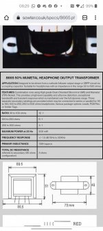
https://www.sowter.co.uk/specs/8665.php
Attachments
Of course 113v would be at 0mA.I just looked at the dc-situation, so the situation without any ac-signal. The anode dissipation is given by: Pa = Ia x Va. The outcome should not violate the maximum anode dissipation as stated in the datasheets.
I don't really understand how you used the loadline calculator. I don't even know if/how this calculator can be used for SRPP circuits. But I would think that the working point (the situation without ac-signal) should be on the loadlines. The working point as calculated by me is 17 mA at 113 V. But I don't see that point on your loadlines (in your loadlines Ia = 0 mA at 113 V and V = 21 V at Ia = 17 mA).
It's a resistive loaded stage, not reactive - the transformer isn't on the plate and does not see any DC.
It's merely a coupling device/load.
I did write that I'm not sure about the meaning of a ratio of 12:1 for this specific transformer. But I searched a bit more on the Sowter site and here they write that the transformers primary is meant for 10K.I believe it to be the impedance ratio as that's the sole purpose of these transformers, not to mention most headphone amps, being of the OTL variety, dealing with short and very steep AC loadlines..
This SSRP powerstage I lifted off of John Broskie's TubeCad, from an OTL design for his 300Ω headphones, to which I added the impedance matching sowter transformers, allowing me to use my own 70Ω Sennheisers or anything else between 30-600Ω.
So the output stage can see impedances between 360-2400Ω depending on the phones and combination of secondary coils selected.
https://www.sowter.co.uk/specs/8665.php
Sowter 8665
The ratio of 12:1 is meant for secondary impedances ranging from 30 to 100 Ohm. With the primary being 10K, this corresponds with turns ratio's of 18.26:1 (for 30 Ohm) and 10:1 (for 100 Ohm). This for me is an indication that the 12:1 ratio is the turns ratio.
But you could ask Sowter to know for sure.
- Home
- Amplifiers
- Tubes / Valves
- My Newly Scratch-Built Tube Headphone Amplifer