So I'm in the process of refurbishing that 60s made Vidaire Catalina tube amp.
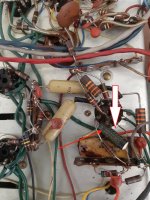
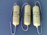
Strangely, there are 3 different types of capacitors there, all carrying the same rating of 0.1uf/400v
Can anyone explain why they used different types of caps while they are all of the same ratings? Is there a specific reason for using different types?
Around each of the 6AN8 tube there is one huge yellow 0.1uf/400v cap, along with two smaller yellow 0.1uf/400v caps.
What new caps exactly should I use at each position? Is the bigger paper cap polarized? it does have a black ring on one side...
The "death cap" is also a 0.1uf/400v, also of a different type. I already removed it but wondering why they are all different?
Also... there's one 3VDC/50uf polarized cap around those 6AN8. A 3v cap on a tube? does it make sense or am I missing anything... can it just be replaced with a 47uf/16v electrolyte?
Thanks!
Attachments


Last edited:
Those are leaky paper caps, replace them all with polypropylene film caps.
The low voltage electrolytic also will be bad by now, use 16V or higher.
The low voltage electrolytic also will be bad by now, use 16V or higher.
Just thinking aloud while my solder melting temperature coffee cup cools down a little.
1) yes, they are different, but 2 of them look as replacements from different eras.
2) the almost vertical waxed paper cap on top is the most primitive and "should" be leaky by now.
If not yet, an ticking time bomb.
3) the one on the left "looks" like a Philips Family (brands vary according to Country) "mustard" cap.
A very good Polyester type which is still valid today.
Being "modern" means it´s smaller, and definitely much better, I trust even a 50 y.o. one, unless proven defective.
4) the one in the middle loo0ks like some intermediate vintage.
5) in "the old days" electrolytic technology was very primitive, you traded capacitance for votage all the time, tolerance was terrible, the works.
In the late 60´s I found and used lots of 6V caps, meant for transistor radios, not surprised that somewhat earlier 3V ones were worth making.
Today, 16V is the usual minimum, simply "because they can", and you can hardly find lower voltage ones except in some niche applications (some motherboards, etc.).
Replaced the two black 50uf/3v polarized with Nichicon electrolytes, placed two 100uf/63v in series to create 50uf. Can already hear a big improvement.
I guess I should keep those 4 "mustard" caps?
The bigger, "vertical" wax caps are leaking wax all over, guess these should be replaced. So, are these polarized or non-polarized caps?
Should I look for paper-in-oil newer caps as a replacement? anything else which is specific for audio applications or tube amps?
I'm not quite sure why they used 400v caps in this location while I measure just a few dozen volts across them.
Use 400VDC polypropylene film capacitors. Vishay-Sprague 715P or 716P are fine.The bigger, "vertical" wax caps are leaking wax all over, guess these should be replaced. So, are these polarized or non-polarized caps?
Should I look for paper-in-oil newer caps as a replacement?
Should these work well? sound-wise...
https://www.ebay.com/itm/333073738721?hash=item4d8cbdebe1:g:0IcAAOSwdfVcZa3d
I read that those "mustard" caps are highly sought after and should sound especially good (Mullard, used in 60s Marshalls?)
Would you recommend keeping them?
And can I just replace them with the same 715P ones I'll replace the bigger cap with?
The 716P is like a 715P, but with copper leads instead of steel.Should these work well? sound-wise...
https://www.ebay.com/itm/333073738721?hash=item4d8cbdebe1:g:0IcAAOSwdfVcZa3d
I read that those "mustard" caps are highly sought after and should sound especially good (Mullard, used in 60s Marshalls?)
Would you recommend keeping them?
And can I just replace them with the same 715P ones I'll replace the bigger cap with?
I read that those "mustard" caps are highly sought after and should sound especially good (Mullard, used in 60s Marshalls?)
Would you recommend keeping them?
I have retained the Mullard "mustard" caps in my valve amp renovations. They are very reliable.
The 3 volt cap was probably a cathode bypass on an input stage. You don’t normally see a lot of voltage but you can’t get 3V caps suitable for audio anymore so you may as well use 16. If the cap was dried out it will lower the gain. If there was feedback, replacing the cap will restore the original amount of feedback (improve distortion and frequency response).
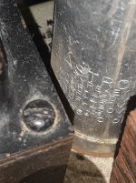
I'd also leave those Philips foil capacitors, arrowed red in your 2nd pic, and the corresponding pair in the other channel. Those unreliable and leaky wax paper capacitors from pic 1, arrowed red in pic 2, and beneath the cathode combination in pic 3 urgently need to be replaced by modern film ones.
Best regards!
Best regards!
Oh I thought the pair of two smaller yellow caps on each tube are the "mustard" ones....
The black polarized ones I already replaced by electrolytes. So, leave those pair of red-arrowed ones in pic2, and replace the larger wax one (on pic1), right?
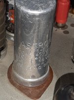
I'm also wondering if there are modern multi-cap replacements that I could use for the big filter caps, or must I use 3 individual electrolytes per multi-cap?
One reads:
10uf/450v
10uf/450v
100uf/50v
The second reads:
40uf/450v
40uf/450v
40uf/450v
The black polarized ones I already replaced by electrolytes. So, leave those pair of red-arrowed ones in pic2, and replace the larger wax one (on pic1), right?
I'm also wondering if there are modern multi-cap replacements that I could use for the big filter caps, or must I use 3 individual electrolytes per multi-cap?
One reads:
10uf/450v
10uf/450v
100uf/50v
The second reads:
40uf/450v
40uf/450v
40uf/450v
Attachments
I'm also wondering if there are modern multi-cap replacements that I could use for the big filter caps, or must I use 3 individual electrolytes per multi-cap?
You're unlikely to get the exact same values in a triple capacitor can (although there may be some flexibility with the values depending on position in the circuit).
And, they're unlikely to come cheap! For example: https://www.tubeampdoctor.com/en/40uf-450v-40uf-400v-30uf-350v-solder-or-clamp-mount?c=70
Would someone be able to explain the huge 0.1uf/400v wax cap on pic1?
When I measure the voltage across it I get 27v DC... why did they use a 400v cap there??
Also, are you all sure this is a non-polarized cap?? asking as it does have a black ring on one side, and the DMM shows positive voltage if I place the negative probe on the ring side, and the positive one on the other side, and voltage becomes negative if I reverse them... Is possible that I should/could use a regular 0.1uf/50v electrolyte there, or even a 0.1uf/100uf?
Attachments
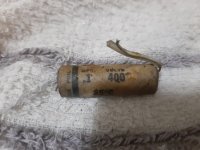
The black ring indicates the terminal that is connected to the outer foil of the capacitor.
The experts will tell you that this determines which way round the capacitor should be connected in a particular circumstance.
It is not a polarised capacitor.
The experts will tell you that this determines which way round the capacitor should be connected in a particular circumstance.
It is not a polarised capacitor.
Information on outer foil marker here: https://www.aikenamps.com/index.php/where-to-connect-the-outside-foil-on-capacitors
Thanks, I ordered Orange 715P to replace them with. But I have to say, I've just replaced one of those wax caps with another, old 0.1uf/400v cap that I had and the sound quality has dropped dramatically. It's possible that they have a certain, warm character to them, will know better once I have the 715P...
Maybe at least one of your .1µF/400V capacitors is defective. I suppose the wax paper one is leaky and compromises the operation point of the following tube.
Best regards!
Best regards!
- Home
- Amplifiers
- Tubes / Valves
- 3 different cap types, all of the same rating? what replacement to use?