I open this thread hoping for some advice that can help me with my first tube project.
My level as an electronic is below 1, so I ask for a little understanding and patience, I do not speak my native language, in short, everything points to that I'm getting into one of my usual mess, in any case, thanks in advance for your interest.
For some time now I have been enjoying an amplifier that I built with an Icepower board, I really like the way it sounds, but the time has come to go further and I have thought of including a tube stage to get some of the desired harmonics and humanize the Icepower a little bit.
I have made a design that I am already testing, I think it sounds pretty good, but I doubt that I got it right the first time, surely there is much room for improvement.
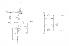
It is a cathode follower with ECC99, I have mixed several ideas that I have been finding in the forum in order to fit it in the power rails that the Icepower provides me.
I have a +57v/-57V symmetrical rail and a +12v/-12v symmetrical rail.
The input impedance of the amplifier is 38Kohm.
I take this opportunity to thank the people of this forum from whom I have borrowed the designs, I hope I have not overreached in any case, if so please do not hesitate to let me know about it.
Thank you all, best regards.

My level as an electronic is below 1, so I ask for a little understanding and patience, I do not speak my native language, in short, everything points to that I'm getting into one of my usual mess, in any case, thanks in advance for your interest.
For some time now I have been enjoying an amplifier that I built with an Icepower board, I really like the way it sounds, but the time has come to go further and I have thought of including a tube stage to get some of the desired harmonics and humanize the Icepower a little bit.
I have made a design that I am already testing, I think it sounds pretty good, but I doubt that I got it right the first time, surely there is much room for improvement.
It is a cathode follower with ECC99, I have mixed several ideas that I have been finding in the forum in order to fit it in the power rails that the Icepower provides me.
I have a +57v/-57V symmetrical rail and a +12v/-12v symmetrical rail.
The input impedance of the amplifier is 38Kohm.
I take this opportunity to thank the people of this forum from whom I have borrowed the designs, I hope I have not overreached in any case, if so please do not hesitate to let me know about it.
Thank you all, best regards.
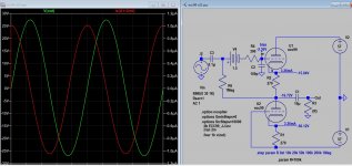
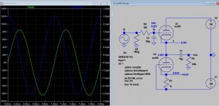
I've redrawn the schematic to make it a bit easier (for me) to grasp.
The circuit looks like the last stage of the Aikido concept (but without noise injection to the grid of the lower half of the ECC99). Because of the power supply arrangement, the input and output are at ground potential.
The sections of the ECC99 are working with less than 50 V between their cathode and anode. I estimate the current to be about 8 mA, giving a cathode voltage only 0.8 V (so a bias of only -0.8 V). Since grid current already starts at about -1.3 V, I would not run an ECC99 this way.
Attachments
In fact I measured 50.4v between cathode and anode, the current should be a little less than 7mA.

I made a (real) cathode follower preamp with 6N6P and a current source, couldn't get it to stop oscillating...
Currently it is sounding fine, perhaps I expected the second order harmonics contribution to be more evident, but there is no background noise and I detect no audible distortion, it is even too transparent (I wished for more valve warmth).
My fear is that there are hidden evils, which I do not detect, maybe the ECC99s die after a short time, or break down the Icepower.
My fear is that there are hidden evils, which I do not detect, maybe the ECC99s die after a short time, or break down the Icepower.
I would think that your circuit would work better with higher B+ (something like 240 V in total, or +120 V and -120 V with your power supply arrangement) and cathode resistors of 150 Ohm instead of 100 Ohm. Those are values Broskie often uses in his Aikdo circuits with the ECC99. This will higher the cathode voltages to over 2 V. Under those circumstances grid current will not flow with line level signals.I have had an Aikido kit for years with ECC99, and I like it a lot, that's why I chose ECC99 for this buffer.
What am I doing wrong so that I can't use this tube in these conditions?
If I understand the workings of this circuit well enough, I think its a true buffer, in the sense that it has a 'gain' of just under 1.
For me it was important to use the +-57v power rails provided by ICEpower, and not to incorporate a transformer to the chassis, I even thought at some point about interposing a voltage doubler.
Thanks Koonw, your approach has me very intrigued, I didn't know it was possible to do such a thing.
Introducing this battery does not imply an increase in noise?
I suppose this could be done by injecting a voltage of 1.5v at this point, for example get it in a regulated manner from one of the power supplies.
Introducing this battery does not imply an increase in noise?
I suppose this could be done by injecting a voltage of 1.5v at this point, for example get it in a regulated manner from one of the power supplies.

Undoubtedly, you are absolutely right, please excuse my clumsiness, I do not write in English, I am pulling Google translate, this added to my low technical level, and surely to an excess of boldness when requesting your attention ends up causing possible confusion.
My two comments about the possible noise and about the possibility of replacing the battery with a fixed current supply should have been more separated, they are different conclusions, one is a question that came to mind when I saw the battery in the same signal input, the second is an occurrence when imagining in an installation of a perishable battery in the circuit.
I hope I have found the right words, I appreciate your interest and your help very much.
I will test your proposal, it could be a very interesting solution.
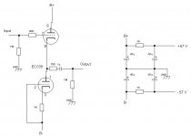
Your circuit is fine, but I would run at lower current so you can increase the bias, and you do not need the upper bias resistor. Try 5mA, 1V bias (use 1k bias resistor). No need for a battery, it is a cathode follower so it already has plenty of headroom.The sections of the ECC99 are working with less than 50 V between their cathode and anode. I estimate the current to be about 8 mA, giving a cathode voltage only 0.8 V (so a bias of only -0.8 V). Since grid current already starts at about -1.3 V, I would not run an ECC99 this way.
Attachments
Last edited:
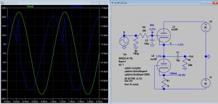
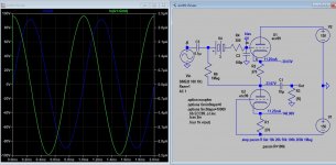
This is the sim result of Merlin's suggestion, but current is <2mA with 1k resistor, nevertheless might be a start point to tweet the sound to your satisfaction.
If you were to drive a tube amp it would be enough, but it can not drive an output stage like 300b because of PSU limitation. If your want more headroom, more current you need higher bias and PSU. Btw this is a White cathode follower..how the sound of the two versions compared I don't know.
If you were to drive a tube amp it would be enough, but it can not drive an output stage like 300b because of PSU limitation. If your want more headroom, more current you need higher bias and PSU. Btw this is a White cathode follower..how the sound of the two versions compared I don't know.
Attachments
Last edited:
That's not a White cathode follower, it's just a cathode follower.Btw this is a White cathode follower..how the sound of the two versions compared I don't know.
I tried Merlinb's proposal, I immediately noticed that the Tube sound started to appear, better crosstalk, a little more "meat", this seems to be the way to go.
Unfortunately the ICepower is silenced after 8 or 10 minutes of work, I do not think it is because of excess consumption, the 1200AS2 supplies 5 amps in each 57v rail, 10 A in total, maybe it is some DC component in the signal, at a given moment the signal stutters and is silenced, just restart the amplifier to return to normal, this happens in any channel randomly.
Unfortunately the ICepower is silenced after 8 or 10 minutes of work, I do not think it is because of excess consumption, the 1200AS2 supplies 5 amps in each 57v rail, 10 A in total, maybe it is some DC component in the signal, at a given moment the signal stutters and is silenced, just restart the amplifier to return to normal, this happens in any channel randomly.
- Home
- Amplifiers
- Tubes / Valves
- ECC99 buffer for low anode voltage