All,
I'm going to start building RJM's 6dj8 phono preamp soon. I've built the VSPS phono stage and the Wyn Palmer phono stage ( like both a lot!), but those had build guides and circuit boards. This will be my first point-to-point amp. I have a few questions and was hoping those with more experience would be able to help:
Dan
I'm going to start building RJM's 6dj8 phono preamp soon. I've built the VSPS phono stage and the Wyn Palmer phono stage ( like both a lot!), but those had build guides and circuit boards. This will be my first point-to-point amp. I have a few questions and was hoping those with more experience would be able to help:
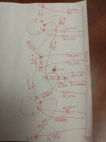
- Does the attached layout of one channel of the amplifier circuit look ok? I've read that layout is very important for tube phono stages to be quiet, but don't exactly know what that implies for the layout of the amplifier section. I tried to set everything up with the minimal number of connections and short signal paths. I don't think I'll need any jumper wires. Also, the two rectangles between the tubes are terminal strips, just so I won't have any floating point connections.
- Does the grounding scheme look OK? My plan will be each channel will have a ground bus, and then those ground busses will be wired to a single star ground point on the chassis. The power supply ground will also be going to that star ground point, which will then go to the ground prong on the power inlet.
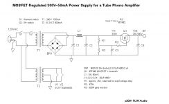
- The power supply will be in the same chassis. I'm planning to try a variant of Eli Duttman's power supply. I will use the same transformer (Allied 6k1vf) and his plan for the B+ to get a regulated DC voltage of 250V for B+. The Allied 6k1vf transformer has a 6.3v winding for the heater filaments of the 6dj8 tubes. So my plan is to first try wiring the 6.3v secondaries directly to the heater filaments. If that's noisy (excess hum?), I will try an artificial center tap or humdinger on the heater filaments. If all of that fails, I'll have to figure out how to create a regulated DC voltage for the filaments
- To start, I'm planning on using a pair of 6922 tubes that I have, just to check if the amp is working. Does that sound OK? My understanding from a bit of research is that the 6922 tube is equivalent to the 6dj8, maybe even built to tighter specifications, but I'm not sure. I could get a pair of 6dj8 tubes if that's advisable once I verify the circuit works.
- My understanding is that pin 9 connects to an internal shield between the two triodes contained in the glass envelope. Should I attach pin 9 to ground, so the shield is grounded?
Dan
Attachments
I would connect the bottom side of C5 straight to the shield of the input connector and minimize the area of the loop enclosed by C5 and R2.
Hi MarcelvdG,
Thanks for the comment. Unfortunately, I'm not exactly sure what you mean. Which is the "bottom side" of C5? And which is the input connector?
Maybe this is what you mean: instead of running C5 all the way to pin 8, I can just connect it to the lead between pin 8 and R3. This way there could effectively be no loop formed by R2 and C5.
Also, just so I understand: why is a loop formed by R2 and C5 bad? Is there some sort of radiating AC current?
Thanks!
Dan
I mean the negative (ground) side of C5. There is a cinch connector somewhere that connects to R2, I would connect the ground side of C5 straight to the ground lug of that cinch connector.
Usually your mains transformer and any nearby mains wiring will radiate 50 Hz or 60 Hz (depending on where you live) varying magnetic fields that are notoriously difficult to get rid of by shielding. Those fields will induce 50 Hz or 60 Hz AC voltages in any loop. The smaller the loop area, the smaller the voltage, so the trick is to keep any loops that are sensitive to 50 Hz or 60 Hz hum very small.
The most sensitive loop in your amplifier is the one from the input cinch connector via R2 to pin 7 of the valve, to pin 8 of the valve and via C5 and C5's ground connection back to the input cinch connector, so you have to keep that as small as practical.
Marcel's advice is spot on.
Sorry to pile on top of that, but...
- I would make sure R2 is located as close to the actual pin 7 as possible, if not soldered right to the socket pin. That's a grid stopper resistor, which is meant to suppress any tendency for oscillation due to wiring inductance from the 6DJ8 grid to elsewhere.
- The above is also relevant to R8 going to pin 7 on the second stage 6DJ8.
- Both of the above are also relevant to the other channel grid stopper resistors going to pin 2 of the 6DJ8s.
Pin 9 of both 6DJ8s should be connected to ground. Exactly where? I would say signal ground (not straight to chassis), but perhaps someone else will know more about this than I do.
6922 tubes are basically 'special quality' 6DJ8. It can be considered a drop-in equivalent. There are minor differences, but nothing that will be critical in this circuit.
Are you floating your heater supply above ground? The triode in a 6DJ8 having pins 6, 7 and 8 can only withstand 50V max from cathode to heater. Both triodes in the 6922 have max cathode to heater voltage of 100V. Perhaps float the heater suppy up +35V. That tends to reduce hum pickup from the heater supply.
That's all I can think of at the moment. Happy soldering!
Hi Marcel,I mean the negative (ground) side of C5. There is a cinch connector somewhere that connects to R2, I would connect the ground side of C5 straight to the ground lug of that cinch connector.
Usually your mains transformer and any nearby mains wiring will radiate 50 Hz or 60 Hz (depending on where you live) varying magnetic fields that are notoriously difficult to get rid of by shielding. Those fields will induce 50 Hz or 60 Hz AC voltages in any loop. The smaller the loop area, the smaller the voltage, so the trick is to keep any loops that are sensitive to 50 Hz or 60 Hz hum very small.
The most sensitive loop in your amplifier is the one from the input cinch connector via R2 to pin 7 of the valve, to pin 8 of the valve and via C5 and C5's ground connection back to the input cinch connector, so you have to keep that as small as practical.
Thanks again for the helpful comment and for clarifying. One follow up question:
Do you by chance have any pictures or links to these cinch connectors you mention? On my other projects I've just soldered a shielded wire to the 'inside' of the female RCA jack. On this project I was just planning on soldering the lead of R2 directly to that middle 'cup' on the inside of the jack. Kind of like this:
Thanks!
Dan
Hi rongon,Marcel's advice is spot on.
Sorry to pile on top of that, but...
- I would make sure R2 is located as close to the actual pin 7 as possible, if not soldered right to the socket pin. That's a grid stopper resistor, which is meant to suppress any tendency for oscillation due to wiring inductance from the 6DJ8 grid to elsewhere.
- The above is also relevant to R8 going to pin 7 on the second stage 6DJ8.
- Both of the above are also relevant to the other channel grid stopper resistors going to pin 2 of the 6DJ8s.
Pin 9 of both 6DJ8s should be connected to ground. Exactly where? I would say signal ground (not straight to chassis), but perhaps someone else will know more about this than I do.
6922 tubes are basically 'special quality' 6DJ8. It can be considered a drop-in equivalent. There are minor differences, but nothing that will be critical in this circuit.
Are you floating your heater supply above ground? The triode in a 6DJ8 having pins 6, 7 and 8 can only withstand 50V max from cathode to heater. Both triodes in the 6922 have max cathode to heater voltage of 100V. Perhaps float the heater suppy up +35V. That tends to reduce hum pickup from the heater supply.
That's all I can think of at the moment. Happy soldering!
Thanks, this is super helpful. I will take your advice regarding R2 & R8 on both channels.
I will need to do some reading regarding how to float heaters. My power transformer has a 6.3v secondary without a center tap. My plan was to add either an artificial center tap or a humdinger. Do you think elevating the heaters would be preferable to either of those?
Again, thank you for your help!
Dan
Attachments
Elevating the heaters is something you would normally do in addition to a humdinger, rather than as a replacement. That is, make a voltage divider that divides the B+ down to a suitable voltage and connect the centre tap of the heater winding or the humdinger potmeter wiper to it.
Elevating the heaters is supposed to help against the effects of heater emission, that is, the heaters generating free electrons that are then picked up by the cathode or the control grid. When those are negative with respect to the heaters, the electric fields don't drive those electrons towards the cathode and control grid (that is, the cathode and control grid don't act as anodes for the electrons that come from the heater). I didn't notice any effect at all in my phono amplifier, but that could be very dependent on the valves, so I left the heater elevating circuit in anyway.
Elevating the heaters is supposed to help against the effects of heater emission, that is, the heaters generating free electrons that are then picked up by the cathode or the control grid. When those are negative with respect to the heaters, the electric fields don't drive those electrons towards the cathode and control grid (that is, the cathode and control grid don't act as anodes for the electrons that come from the heater). I didn't notice any effect at all in my phono amplifier, but that could be very dependent on the valves, so I left the heater elevating circuit in anyway.
Last edited:
I was thinking of connectors like these:Hi Marcel,
Thanks again for the helpful comment and for clarifying. One follow up question:
Do you by chance have any pictures or links to these cinch connectors you mention? On my other projects I've just soldered a shielded wire to the 'inside' of the female RCA jack. On this project I was just planning on soldering the lead of R2 directly to that middle 'cup' on the inside of the jack. Kind of like this: View attachment 1004376I would be happy to learn if there's a better way to connect to these jacks.
Thanks!
Dan
https://nl.mouser.com/ProductDetail/REAN/NYS367-2?qs=R5cXQUTKuHXVYwwK%2BeCprA==
No idea if they are better or worse than yours.
You probably already know this, but the heater wires need to be twisted. The idea behind that is to minimize the loop area between the heater wires, so they generate as little 50 Hz or 60 Hz magnetic field as possible, and to swap the orientations of the bits of loop area that are still left, so you get a cancellation of the remaining hum fields. I've used professional balanced audio cable for the heater wires in my phono preamplifier, that cable is twisted as well as shielded. The shielding doesn't do much against 50 Hz or 60 Hz magnetic fields, but it shields any electric fields.
The supply transformer needs to be as far from the inputs as it can be, again because of 50 Hz or 60 Hz magnetic fields. It can also be useful if you can turn it, to see what orientation leads to the smallest hum. That's assuming it's an old-fashioned EI-transformer, there is not much point turning toroidal transformers around their axis.
The supply transformer needs to be as far from the inputs as it can be, again because of 50 Hz or 60 Hz magnetic fields. It can also be useful if you can turn it, to see what orientation leads to the smallest hum. That's assuming it's an old-fashioned EI-transformer, there is not much point turning toroidal transformers around their axis.
Thanks, Marcel. Those are in fact exactly what I use. When you said "cinch" connector I thought maybe you were referring to some sort of solderless connector using pins and sleeves or something. Thanks!I was thinking of connectors like these:
https://nl.mouser.com/ProductDetail/REAN/NYS367-2?qs=R5cXQUTKuHXVYwwK%2BeCprA==
No idea if they are better or worse than yours.
Dan
Yes, thanks -- I am aware that the heater wires need to be twisted, but it's great to read your explanation of why, etc. Thanks. I've been reading this site which has a nice description of optimal layout of heater wiring.You probably already know this, but the heater wires need to be twisted. The idea behind that is to minimize the loop area between the heater wires, so they generate as little 50 Hz or 60 Hz magnetic field as possible, and to swap the orientations of the bits of loop area that are still left, so you get a cancellation of the remaining hum fields. I've used professional balanced audio cable for the heater wires in my phono preamplifier, that cable is twisted as well as shielded. The shielding doesn't do much against 50 Hz or 60 Hz magnetic fields, but it shields any electric fields.
The supply transformer needs to be as far from the inputs as it can be, again because of 50 Hz or 60 Hz magnetic fields. It can also be useful if you can turn it, to see what orientation leads to the smallest hum. That's assuming it's an old-fashioned EI-transformer, there is not much point turning toroidal transformers around their axis.
My transformer is the old-fashioned variety, so I will play with orientation if the first iteration produces hum.
Thanks! Dan
Again, Thanks, Marcel. This is very helpful. Merlin Blencowe's website also has a nice description of how to elevate the heater voltage.Elevating the heaters is something you would normally do in addition to a humdinger, rather than as a replacement. That is, make a voltage divider that divides the B+ down to a suitable voltage and connect the centre tap of the heater winding or the humdinger potmeter wiper to it.
Elevating the heaters is supposed to help against the effects of heater emission, that is, the heaters generating free electrons that are then picked up by the cathode or the control grid. When those are negative with respect to the heaters, the electric fields don't drive those electrons towards the cathode and control grid (that is, the cathode and control grid don't act as anodes for the electrons that come from the heater). I didn't notice any effect at all in my phono amplifier, but that could be very dependent on the valves, so I left the heater elevating circuit in anyway.
Does this sound like a reasonable plan: start w/ the humdinger on the heater wiring, and if needed, add in a voltage divider to elevate the heater voltage.
Thanks!
Dan
I'm searching for some good pictures of other peoples' phono preamp wiring, particularly the input, connections to the first tube, and grounding. Does anyone have any good pictures of these sections on a tube phono preamp that would help illustrate good layout? Thanks!
Dan
Dan
Hi Marcel,I mean the negative (ground) side of C5. There is a cinch connector somewhere that connects to R2, I would connect the ground side of C5 straight to the ground lug of that cinch connector.
Usually your mains transformer and any nearby mains wiring will radiate 50 Hz or 60 Hz (depending on where you live) varying magnetic fields that are notoriously difficult to get rid of by shielding. Those fields will induce 50 Hz or 60 Hz AC voltages in any loop. The smaller the loop area, the smaller the voltage, so the trick is to keep any loops that are sensitive to 50 Hz or 60 Hz hum very small.
The most sensitive loop in your amplifier is the one from the input cinch connector via R2 to pin 7 of the valve, to pin 8 of the valve and via C5 and C5's ground connection back to the input cinch connector, so you have to keep that as small as practical.
Sorry to pick nits on this -- Should R3 also be connected directly from Pin 8 of the first tube to the ground connection on the RCA input?
I'm just trying to understand your suggestion better. If the loop "Input --> pin 7 via R2 --> Gnd via C5 --> back to input via ground connection" is sensitive, isn't also the same loop substituting R3 for C5?
Thanks! Dan
Yes, preferably R3 should also be connected straight to the RCA input ground, but it is about 15.71 times less critical than C5 at 50 Hz, 18.85 times at 60 Hz.
When you look at the impedances and calculate how 50 Hz or 60 Hz current divides between R3 and C5, you find that at 50 Hz, 99.798 % of the current goes through C5 and 6.3533 % through R3. (The reason it doesn't add up to 100 % is the 90 degree phase difference between the currents, it does add up to 100 % when you use Pythagoras' theorem.) The main AC current loop is therefore the loop via C5. Conversely, any voltage induced in the wiring to and from R3 also has 15.71 (or 18.85) times less effect than voltage induced in the wiring to and from C5.
When you look at the impedances and calculate how 50 Hz or 60 Hz current divides between R3 and C5, you find that at 50 Hz, 99.798 % of the current goes through C5 and 6.3533 % through R3. (The reason it doesn't add up to 100 % is the 90 degree phase difference between the currents, it does add up to 100 % when you use Pythagoras' theorem.) The main AC current loop is therefore the loop via C5. Conversely, any voltage induced in the wiring to and from R3 also has 15.71 (or 18.85) times less effect than voltage induced in the wiring to and from C5.
Thanks! this is very helpful!!Yes, preferably R3 should also be connected straight to the RCA input ground, but it is about 15.71 times less critical than C5 at 50 Hz, 18.85 times at 60 Hz.
When you look at the impedances and calculate how 50 Hz or 60 Hz current divides between R3 and C5, you find that at 50 Hz, 99.798 % of the current goes through C5 and 6.3533 % through R3. (The reason it doesn't add up to 100 % is the 90 degree phase difference between the currents, it does add up to 100 % when you use Pythagoras' theorem.) The main AC current loop is therefore the loop via C5. Conversely, any voltage induced in the wiring to and from R3 also has 15.71 (or 18.85) times less effect than voltage induced in the wiring to and from C5.
Dan
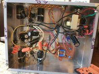
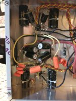
Just a quick update: I built the amp -- pictures attached. I'd be grateful for any critiques, comments, suggestions. It's not pretty. This is my first amp build from a schematic w/o guidance or hand-holding. If I at some point re-do the circuit, I would space components out a bit wider so that they'd fit together a bit more easily and not require the jumper wires I had to place. I don't yet know if hum will be an issue (see below), but I could imagine a few layout changes that might reduce hum.
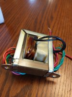
Things didn't go as planned on initial power up. I plugged it in and turned it on and no immediate explosions, so I was cautiously optimistic. As I was checking voltages, something started to smell kind of "burney," kind of a melting plastic smell. I shut it down, and noticed that part of the power transformer was turning dark brown. I didn't really get much useful information while the amp was on. The heater voltage was low, about 2.8 volts. I didn't have time to check what the B+ was.
After a short break to regroup, I took out the power transformer and measured resistance on the windings. The resistance between the two primary leads is about 30 ohms, the resistance between the two high voltage secondary leads is about 4 ohms, and the resistance between the two heater secondary leads is 0 ohms. Do any of those seem incorrect/possibly the cause of the overheating?
I've ordered a (beefier) replacement transformer (Hammond 269AX). But before I just throw it in there I was hoping that someone might have some insight into what went wrong, whether it could have been a faulty transformer, or whether something else might be off in the circuit. I'm not sure what I can check w/o the transformer in and the power on, but if you have any ideas, please let me know and I'll do it.
One additional question: Can I run the power supply section w/o it being connected to the amplifier section? My power supply is the Eli Duttman design (scroll to the end of page 1 or go to page 2 for the power supply schematic). If I can check the power supply unloaded, I'd at least be able to check if it's working correctly.
Thanks for all of your help!
Dan
Attachments

Pity about the transformer. Sounds like it was underrated or there was a short somewhere in the circuit.
Regarding testing the supply: series regulator ICs usually have a minimum load current requirement. It can be found in their datasheets, albeit sometimes implicitly: the specifications are then guaranteed over some output current range and the lower limit is the minimum load current. Connect resistors that draw the minimum load current or a bit more and you can test the supply without the amplifier.
Regarding testing the supply: series regulator ICs usually have a minimum load current requirement. It can be found in their datasheets, albeit sometimes implicitly: the specifications are then guaranteed over some output current range and the lower limit is the minimum load current. Connect resistors that draw the minimum load current or a bit more and you can test the supply without the amplifier.
- Home
- Source & Line
- Analogue Source
- Building the RJM 6dj8 phono preamp