dear all,
i am joining with a question that is probably simple for many of you but i werent able to figure it out.
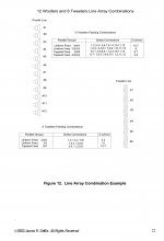
i was trying to make a concrete wiring diagram of james giffitn’s tapered line array example that he mentiones in his great 2003 paper and of which i join the relevant page here.
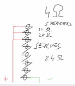
there is also my humble attempt to draw a diagram for the first two (uniform feeds) wirings (3 groups of four in parralel and simultanously 4 groups of three).
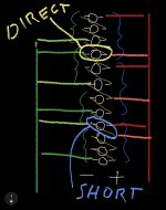
can anybody help me with that, please? i seem to be getting all sorts of short circuits as you need to do multiple series and parralel wirings to the same speakers in the array. we see several problems there: direct connection of several speakers (not series any more only) and shorts.
many thanks in advance for your help. guess this is also interesting for other people.
best wishes to all members
i am joining with a question that is probably simple for many of you but i werent able to figure it out.
i was trying to make a concrete wiring diagram of james giffitn’s tapered line array example that he mentiones in his great 2003 paper and of which i join the relevant page here.
there is also my humble attempt to draw a diagram for the first two (uniform feeds) wirings (3 groups of four in parralel and simultanously 4 groups of three).
can anybody help me with that, please? i seem to be getting all sorts of short circuits as you need to do multiple series and parralel wirings to the same speakers in the array. we see several problems there: direct connection of several speakers (not series any more only) and shorts.
many thanks in advance for your help. guess this is also interesting for other people.
best wishes to all members
PHP:
Attachments
3 groups of 4 drivers and 4 groups of 3 are not shaded, you do realize that right?
I would advise you to use/download some tool like bwaslo's Xsim to get more grip on the matter.
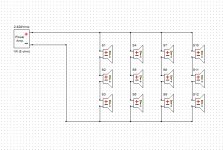
The example I upload of a 4 groups of 3 series driver is created with that program:

I tried to make it a clear and readable schematic you can follow. it features the second option: s1,s2,s3/s4,s5,s6/s7,s8,s9/s10,s11,s12 making it 6 ohm if the basic driver is an 8 ohm unit.
Hopefully you'll be able to create the first (3 groups of 4 series) example on your own after studying this one? And maybe move on to the shaded examples after that. 😉
I would advise you to use/download some tool like bwaslo's Xsim to get more grip on the matter.
The example I upload of a 4 groups of 3 series driver is created with that program:
I tried to make it a clear and readable schematic you can follow. it features the second option: s1,s2,s3/s4,s5,s6/s7,s8,s9/s10,s11,s12 making it 6 ohm if the basic driver is an 8 ohm unit.
Hopefully you'll be able to create the first (3 groups of 4 series) example on your own after studying this one? And maybe move on to the shaded examples after that. 😉
Attachments

many thanks wesayso.
but i dont see how i could use your suggestion as the same 12 speakers are simultanously connected in series groups of 3 AND 4 which are then connected in parrallel SIMULTANOUSLY as i understand it.
best wishes
but i dont see how i could use your suggestion as the same 12 speakers are simultanously connected in series groups of 3 AND 4 which are then connected in parrallel SIMULTANOUSLY as i understand it.
best wishes
3 groups of 4 drivers and 4 groups of 3 are not shaded, you do realize that right?
sorry, i dont understand what you are trying to say here “not shaded”.
best wishes
oliver
There's a document that accompanies the Linus project called LinusXvr.doc.
Do you have that? It clearly shows how to wire the tapered array.
Both configurations posted by wesayo are NOT tapered arrays. 🙂
Dave.
Do you have that? It clearly shows how to wire the tapered array.
Both configurations posted by wesayo are NOT tapered arrays. 🙂
Dave.
Last edited:

sorry, i dont understand what you are trying to say here “not shaded”.
best wishes
oliver
Hi Oliver, in the two samples you asked about all drivers are driven equally loud. That means it is not tapered. Each group of drivers forms the same load, driven in parallel they each get exactly the same power to handle.
In a tapered array like this, the central drivers are the loudest, from there on each group of drivers around the central 2 drivers will be a little less loud, or in other words: shaded.
Scott has posted an example of a shaded array.
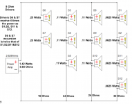
The drivers s6 & s7 will be the loudest group (they form a 16 ohm load)
The groups around that: s3, s4, s5 and s8, s9, s10 (both forming 24 ohm groups) will be a bit less loud.
The most upper and lower drivers that are connected in series, s1, s2, s11, s12 (together a 32 ohm load) will be the least loud.
Together they make a shaded array.
Oliver,
Thanks for the personal e-mail via the DIYAudio system. Scottmoose and wesayso in their posts above have drawings that better show a tapered array (Scott the 2/3/3/4 driver tapered array that I originally presented in the nearfield line array white paper) and wesayso a uniform feed wiring which have the same power level to all drivers for a 3/3/3/3 feed. It is important, as wesayso stated, to follow the numbering of the specific drivers as they are positioned in the stack of drivers to know how the wiring is achieved. I recommend that you build a uniform feed (either 3/3/3/3 or 4/4/4 unless you have a compelled desire to taper the array.
If you think this is problem, understand how my curved array (Modified CBT24) that I designed a few years is wired. The Modified CBT24 array is shaded to approximate a Legendre series--a 3 step approximation in my case. In post #66 in my diyaudio thread on the Modified CBT24 wiring I link a pdf diagram that shows how a truly tapered array is implemented. The Modified CBT24 requires a tapered feed so that the proper time delays and amplitude levels are achieved.
See: My New Line Array--It's a Modified CBT24
Jim
Last edited:
Jim,I recommend that you build a uniform feed (either 3/3/3/3 or 4/4/4 unless you have a compelled desire to taper the array.
Glad you checked in to clarify!
As you wrote in 2003 "If tapering is taken to the limit, the sound image will trend toward a point source."
Using a straight line array to emulate a point source has drawbacks- while reducing the level of the outer drivers makes the center drivers relatively louder, it also reduces the line array effectiveness and throws away sensitivity, increasing excursion (and distortion) in the center drivers, as well as potentially burning those voice coils.
As Oliver may potentially use his line array drivers down to 40 Hz, definitely something to consider.
The attachment below illustrates the power received in each driver in the 2/3/3/4 tapered feed you described, the center drivers receiving +6 dB compared to the outer.
Art
Attachments
Last edited:
In 2008, I purchased a pair of Renkus Heinz ICX7 line arrays using 7 co-ax drivers, the tweeters were power shaded, the outer being around -10dB if I recall correctly.
Although they sounded good, effectively this required the center tweeters to provide most of the high frequency output, they literally "melted down" during an alignment test in my first use of them as delay speakers on an outdoor stage.
Renkus Heinz subsequently changed the ICX7 internal design completely ;^).
Art
Attachments
Hey guys, i've got a little wine in me, so forgive if i'm lost in space...
But the missing piece in this thread seems to be what kind of line are we talking about?
CBT (Jim's / Keele's shading) or straight (which works with frequency shading, but not with just amplitude shading) ????
But the missing piece in this thread seems to be what kind of line are we talking about?
CBT (Jim's / Keele's shading) or straight (which works with frequency shading, but not with just amplitude shading) ????
many thanks for all these great and helpful posts.
particularly glad and honored that jim himself has also provided some input.
i will definitely check out the links you posted.
my current project are actually CURVED arrays of 21 2.5 “ müller speakers.
so, tapering is part of the design if i understood correctly.
my issues are in fact due to a misunderstanding. i figuered the alternative wirings in the paper were in fact simultanous, which doesnt make sense as i now understand.
i learned a lot of this mistake and am happy to interact with so many smart audio enthusiasts.
thanks again and all the best
oliver
very interesting, weltersys.
would you mind sharing the math for the wattage and excursion calculation?
many thanks for this useful post
regards
oliver
would you mind sharing the math for the wattage and excursion calculation?
many thanks for this useful post
regards
oliver
Jim,
Glad you checked in to clarify!
As you wrote in 2003 "If tapering is taken to the limit, the sound image will trend toward a point source."
Using a straight line array to emulate a point source has drawbacks- while reducing the level of the outer drivers makes the center drivers relatively louder, it also reduces the line array effectiveness and throws away sensitivity, increasing excursion (and distortion) in the center drivers, as well as potentially burning those voice coils.
As Oliver may potentially use his line array drivers down to 40 Hz, definitely something to consider.
The attachment below illustrates the power received in each driver in the 2/3/3/4 tapered feed you described, the center drivers receiving +6 dB compared to the outer.
Art
A 3dB increase doubles power, a 6 dB increase is four times the power.
A 6dB increase in power doubles excursion.
Power in watts is equal to voltage squared divided by the resistance in ohms (Ω).
Series resistance of multiples of the same resistance in ohms (Ω) is simply an addition/multiplication of the values, 2x8Ω=16Ω, 3x8Ω=24Ω, 4x8Ω=32Ω.
In the example, 2.828V was used, a voltage that equals one watt into 8 ohms.
2.828V x 2.828V=8/8Ω=1watt
2.828V x 2.828V=8/16Ω=0.5 watt/2(speakers)=0.25 watts per speaker
2.828V x 2.828V=8/24Ω=0.33/3 (speakers)=0.11 watts per speaker
2.828V x 2.828V=8/32Ω=0.25 watts/(speakers)4= 0.0625 watts per speaker
Total resistance= 1/ (1/R1 +1/R2 +1/R3 +1R4 +etc...)
The total series parallel resistance was 5.65Ω , 2.828V x 2.828V=8/5.65Ω=1.45 watts.
Online calculators like this can do most of the math for you:
Parallel and Series Resistance Calculator-Apogeeweb
Art
Attachments

Last edited:
In my straight array I used frequency shading to keep as many drivers as possible to help out on the bottom end. The advantages compared to a straight unshaded array were clear in simulations.
I do wonder if a shading pattern like that could be used/would work in a CBT as well, I believe it would divide the load better among the drivers (especially at lower frequencies).


The power distribution of the groups can be seen in the right middle graph.
It also shows that the correction needed is without the bumps and dips of crosstalk of the unshaded array.
The correction shape that's left almost is a mirror image of the frequency graph of one driver.
Well, except for the specific line array treats. 😉
I do wonder if a shading pattern like that could be used/would work in a CBT as well, I believe it would divide the load better among the drivers (especially at lower frequencies).
The power distribution of the groups can be seen in the right middle graph.
It also shows that the correction needed is without the bumps and dips of crosstalk of the unshaded array.
The correction shape that's left almost is a mirror image of the frequency graph of one driver.
Well, except for the specific line array treats. 😉
Attachments

Last edited:
tapered feed wiring idea
@ wesayso: many thanks, very helpful.
in my wanderings to solve my impossible problem, i had the following idea of wiring the speakers on the edges of the CBT (see picure).
any idea what effect on resistance and wattage/excursion of the speakers in that configuration? i wonder how the additionnally added speakers would affect wattage/excursion of the first series of 6.
many thanks again
oliver
Attachments
In my straight array I used frequency shading to keep as many drivers as possible to help out on the bottom end. The advantages compared to a straight unshaded array were clear in simulations.
I do wonder if a shading pattern like that could be used/would work in a CBT as well, I believe it would divide the load better among the drivers (especially at lower frequencies).
very interesting idea. very curious to read what jim will say. frequency shading probably allowing a reduction of fullrange tapering?
@ wesayso: many thanks, very helpful.
in my wanderings to solve my impossible problem, i had the following idea of wiring the speakers on the edges of the CBT (see picure).
any idea what effect on resistance and wattage/excursion of the speakers in that configuration? i wonder how the additionnally added speakers would affect wattage/excursion of the first series of 6.
many thanks again
oliver
sorry, this was to thank weltersys… 🙂
Having built shaded, unshaded, curved and CBT arrays, there is no doubt what is "best".
We had these discussions some time ago... each member got his own baby.
Another option: Small, good and cheap, but dynamite class D-amps may serve each column part in a line array instead of passive topology. A 2 x 4way electronic crossover (or more) incl time delay is needed though.
We had these discussions some time ago... each member got his own baby.
Another option: Small, good and cheap, but dynamite class D-amps may serve each column part in a line array instead of passive topology. A 2 x 4way electronic crossover (or more) incl time delay is needed though.
- Home
- Loudspeakers
- Multi-Way
- Jim Griffin tapered line array wiring scheme