Hello Folks. I think this will be the last DIY amp I build. In the last two years this will make 4 amplifiers and 2 pre-amps. MX50SE, L12-2, L20SE and ESP project P101. ESP project 97 pre-amp and Doug Self Preamp from Linear Audio #5.
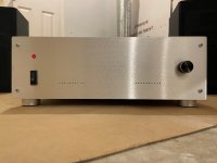
This is the P101 rev C. MOSFET Amp from Elliott Sound.
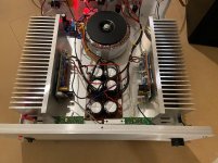
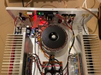
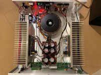
I put it together with all his recommended parts. I ordered the power MOSFET from England, 40-0-40 625va Toroidal from Parts Express, Heatsinks from HeatsinkUSA, purchased the Soft-start and speaker protect boards from DIYaudio. I had a Velleman K4305 VU-Meter kit.
I built the Power supply Filter board as recommended from ESP and added a 12vdc regulator that gets fed from the Pos Rail to power the VU-Meter. I added RL circuits to the outputs using 1.2uH air coils and 10ohm/5watt resistors.
Some spec’s…
Set the bias to 20mA per pair.
Power supply…+60.5/-60.6
20mV ripple across +and- power supply
DC offset: Lt 1.2 mV / Rt 1.1mV
Total weight… 26 lbs.
Elliott is correct, It does sound very good.
Glad to try and answer any questions about the build.
Scott 😀
This is the P101 rev C. MOSFET Amp from Elliott Sound.
I put it together with all his recommended parts. I ordered the power MOSFET from England, 40-0-40 625va Toroidal from Parts Express, Heatsinks from HeatsinkUSA, purchased the Soft-start and speaker protect boards from DIYaudio. I had a Velleman K4305 VU-Meter kit.
I built the Power supply Filter board as recommended from ESP and added a 12vdc regulator that gets fed from the Pos Rail to power the VU-Meter. I added RL circuits to the outputs using 1.2uH air coils and 10ohm/5watt resistors.
Some spec’s…
Set the bias to 20mA per pair.
Power supply…+60.5/-60.6
20mV ripple across +and- power supply
DC offset: Lt 1.2 mV / Rt 1.1mV
Total weight… 26 lbs.
Elliott is correct, It does sound very good.
Glad to try and answer any questions about the build.
Scott 😀
Attachments
Congratulations! You must be enjoying your work and what it does. Looks very neat and clean, professionally executed. So far I have only restored gear, but if I built an amp, I'd start here as well, I assume, with rod elliott's 101. And then a little Hiraga...
That's a pretty amp for sure!
Rod's site has a lot of goodies, I've built some of his designs - all perform excellently of course.
The one project, #99, a Salen-Key subsonic filter, is one I really like.
It's made several of my amps performance elevated, because it effectively eliminates unwanted 0-to-20Hz what I call "noise" that isn't needed for music enjoyment.
And by eliminating those subsonics, the amp is stressed much less, so are woofer cones due to feedback from turntables.
Why stress and use/waste power from an amp at those low frequencies?
More power goes to things I care to hear.
But indeed, your amp is a damn nice job. 😉

Congratulations, excellent job
Where did you source the chassis from?
Par-Metal
They sell on ebay also. Look for Pi Metal Products Inc.
🙂
Big fan of MOSFET amps. I should look at this one. I run my own designed 60W/Exicon amp.
Love those big heat sinks. A trend in modern gear is marginal designs to make them sleek. Bad for durability as every 10 degrees C is half life, as well as improved linearity.
Love those big heat sinks. A trend in modern gear is marginal designs to make them sleek. Bad for durability as every 10 degrees C is half life, as well as improved linearity.
Just took a look. I see it used dominant pole filtering. This is how almost all of them are done, following Erno's original Hitachi design, Haflers etc. Mosfets are hard to keep stable due to their very wide bandwidth, so a safe design. I succeeded in converting to Miller compensation and the improvement is sound was dramatic. Like a veil lifted. It tool a lot of SPICE work and blew up a few pairs before I got it stable.
Nice simple design. Personally, I would only go 50W per pair but I am a big believer in lower current in my outputs, but higher class A region. I also use much larger cap banks with supporting bridge. Another problem with modern amps. I am seeing 60W integrated amps with less bank than I put in a preamp! And they sound like it. Flat and dull!
Nice simple design. Personally, I would only go 50W per pair but I am a big believer in lower current in my outputs, but higher class A region. I also use much larger cap banks with supporting bridge. Another problem with modern amps. I am seeing 60W integrated amps with less bank than I put in a preamp! And they sound like it. Flat and dull!
Just took a look. I see it used dominant pole filtering. This is how almost all of them are done, following Erno's original Hitachi design, Haflers etc. Mosfets are hard to keep stable due to their very wide bandwidth, so a safe design. I succeeded in converting to Miller compensation and the improvement is sound was dramatic. Like a veil lifted. It tool a lot of SPICE work and blew up a few pairs before I got it stable.
Nice simple design. Personally, I would only go 50W per pair but I am a big believer in lower current in my outputs, but higher class A region. I also use much larger cap banks with supporting bridge. Another problem with modern amps. I am seeing 60W integrated amps with less bank than I put in a preamp! And they sound like it. Flat and dull!
He recommended Exicon ECX10N20 and ECX10P20 (available from Profusion PLC in the UK). They only took a week to get here in central IL. Very fast.
This is Elliott's design...
The output stage consists of one or or two pairs of power MOSFETs. The gates are isolated with resistors to prevent parasitic oscillation, and a resistor is used in the source of each MOSFET to help ensure current sharing. Although MOSFETs have a positive temperature coefficient and theoretically will current share properly without any resistance, it is common practice to use the resistors regardless.
The diode and zener combination in each gate drive circuit limits the maximum gate voltage and provides basic overload protection - although MOSFETs are much more tolerant of overload than bipolar transistors, operation into a short circuit is not recommended.
C11 and C12 are used to compensate for the fact that P-Channel MOSFETs have a different (higher) gate-source capacitance than do N-Channel devices. C11 and C12 equalise the capacitance. Do not attempt to operate the amplifier until these capacitors are fitted, as it will oscillate!
Finally, the output section uses a conventional Zobel network. If desired, this can be followed (right at the speaker terminals) by a small inductor with a paralleled resistor, and finally a second Zobel network at the output. This is intended to decouple the amplifier from highly capacitive loads and ensure stability under all normal operational conditions. The use of ultra-low inductance (very high capacitance) speaker leads is not recommended, although the additional output network described will prevent oscillation in most cases. The inductor can be quite small(around 5-10μH is about right), and must be shunted by a parallel resistance of between 2.2 and 10 ohms (10μHgives a -3dB frequency of 71kHz with an 8 ohm load).
I built a few of these and listening to one now...My advice - crank the bias up to 100ma.
The ESP P101, the Hypex NC400 and Krell KSA-50 Clone are my favorite SS amps I built...and in the process of making another F5 - awaiting for more parts)
Computer -> AMR DP777ES DAC -> Aikido 6922/6H30 -> amp -> Quad Esl-988.
The P101 just does everything nicely...
The ESP P101, the Hypex NC400 and Krell KSA-50 Clone are my favorite SS amps I built...and in the process of making another F5 - awaiting for more parts)
Computer -> AMR DP777ES DAC -> Aikido 6922/6H30 -> amp -> Quad Esl-988.
The P101 just does everything nicely...
Last edited:
I built a few of these and listening to one now...My advice - crank the bias up to 100ma.
The ESP P101, the Hypex NC400 and Krell KSA-50 Clone are my favorite SS amps I built...and in the process of making another F5 - awaiting for more parts)
Computer -> AMR DP777ES DAC -> Aikido 6922/6H30 -> amp -> Quad Esl-988.
The P101 just does everything nicely...
That's pretty hot for +-60 volt rails is it not? Does it really make it sound better?
Elliott suggests; A maximum of around 50mA per pair, or 33mV. When using ±56V or less, you can increase the current to 100mA,but this will result in a total quiescent dissipation of up to 22.4W so the heatsink will get noticeably warm.
I'll try 50mA per pair and give it a go.
So I adjusted bias to 25mV per pair (38mA) and yes it does sound much, MUCH better. Close to my Kenwood Basic M2!
Heatsinks are big enough and stay cold.
I did notice my DC offset change though... Lt -21mV, Rt -15mV.
And rail voltage dropped to +/- 59VDC
Thanks john65b for the advice. It really brought the speakers to life.. Much richer, punchier bass and much crisper mids and highs.
Heatsinks are big enough and stay cold.
I did notice my DC offset change though... Lt -21mV, Rt -15mV.
And rail voltage dropped to +/- 59VDC
Thanks john65b for the advice. It really brought the speakers to life.. Much richer, punchier bass and much crisper mids and highs.
Hey, glad to help. Great amps....
If sinks are still cool, you can go higher to 66mv (100ma)...
With 625VA toroid and all that sinking, you have the room. I jacked mine all the way to 280ma before started hearing the power supply ripple and backed it off.
I doubt you will hear any ripple at the 100ma, and may like it even more...
If sinks are still cool, you can go higher to 66mv (100ma)...
With 625VA toroid and all that sinking, you have the room. I jacked mine all the way to 280ma before started hearing the power supply ripple and backed it off.
I doubt you will hear any ripple at the 100ma, and may like it even more...
Last edited:
Biasing most amps for a higher quiescent current up to a point does maintain class A operation longer, with the benefit of eliminating any possible crossover distortion, and the additional loading of the power supply from this improves regulation.
But beware of pushing for a "good thing" and use common sense and understand the overall circuitry (and hardware) involved.
But beware of pushing for a "good thing" and use common sense and understand the overall circuitry (and hardware) involved.
I adjusted bias to 50mA per pair. Sounds about the same as 38mA but might be the small test speakers I'm using. Still sounds great. Thanks all
90scaraudio,
congratulations on your wonderful build! Everything looks so carefully planned and implemented. Quite a push for me to complete my build of P101🙂.
Thanks for sharing your listening impressions at different bias levels. The simulations I made show that moving from 20mA to 50mA would decrease the distortion level more than two times. While at 1kHz the THD is very low even at 20mA (0.008% @ 5W), it grows steeply with frequency (to 0.18% @ 5W, 20 kHz). I guess what you observed at increased bias level was exactly the improved THD at higher frequencies. Moving much above 50mA though would probably not yield noticeable improvement in sound quality. Of course, this is just what the simulator tells, so I am eager to complete the project and test it at different bias levels too.
Congratulations again and thanks for posting!
Bias setting
First, nice build.
My amp of 10 years failed, lighting screwed up the trany, and boards screwed.
Anyway, been awhile.
Take the Bias reading on A and B, picture, is that a CURRENT or VOLTAGE reading???
Posted on ESP Forum. Said it was CURRENT.
VR1 is a 2K 10turn. What resistance do you have on it, if its no trouble? That will get me ball park, because turning xlockwise I get ZERO and have to stop so I don't blow anything.
Got the 2 100 OHM 5 watt, lamp, and rheostat slowly up to 15+/-volts.
ISTRUCTION:
Carefully advance VR1 - with 0.33 Ohm resistors, the total is 0.66 Ohm, and for 20mA bias you will measure 13.2mV (14 - 20mV is fine) across each resistor pair. You may increase the bias current if it makes you feel better. I suggest a maximum of around 50mA per pair, or 33mV. When using ±56V or less, you can increase the current to 100mA, but this will result in a total quiescent dissipation of up to 22.4W so the heatsink will get noticeably warm.
THANKS
Some spec’s…
Set the bias to 20mA per pair.
Power supply…+60.5/-60.6
20mV ripple across +and- power supply
DC offset: Lt 1.2 mV / Rt 1.1mV
Glad to try and answer any questions about the build.
Scott 😀
- Home
- Amplifiers
- Solid State
- Elliott Sound Project 101 Rev C