On the solid state CCS you may find that you're bumping into the switch off point of the mosfet. That switch on/off may explain some of the distortion.
Try with just a non CCS'd 6as7 version then work from there.
It's possible - Broskie has had 6as7s and other tubes running parallel SE with CCS. You probably want to float the cathode of the 6as7 at about +20V and adjust the biasing for the 6as7 accordingly. The 6as7 is one of the tubes here fixed bias is not recommended.
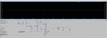
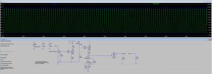
So when i use a 1k cathode bias resistor on the 6as7 i get roughly 62mA and 62V. and when running signal i get about 34% THD... it seems to me that the tube reaches its cutoff point somewhere, the bottom half of the sine wave is very flat. decreasing it down to about 100ohm gave me a THD of around 8% but now we are also consuming peaks of 800mA at 200V so no go...
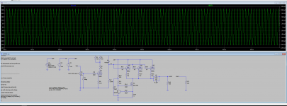
I have attached the steady state as well as with the 2Vrms input of the CCS i would like to have. i might need to have another small resistor after the programming resistor to keep some voltage there when it start going but as you can see we are hitting the cutoff limit of the tube. i've also added the models i'm using for the different fets and tubes.
what do you mean when you say floating the cathode at 20V? To me a floating voltage sound like it doesnt have ground reference.
Attachments

I must ask why you don't just use the "Headwize" design? 150V B+ easily obtainable from a 120V isolation xfmr (cheap)? Double the 6AS7, half the cathode resistors, and voila! An SE HP amp that can drive 16R. Delon voltage doubler for the 6SN7 voltage if you don't want to use 6DJ8.
This was my first headphone amp. I now use a better/more efficient design (because it doubles as a line amp and runs 24/7).
This was my first headphone amp. I now use a better/more efficient design (because it doubles as a line amp and runs 24/7).
Last edited:
Direct Newton iteration for .op point succeeded.
N-Period=all
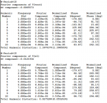
Fourier components of I(rload)
DC component:8.39543e-05
Harmonic Frequency Fourier Normalized Phase Normalized
Number [Hz] Component Component [degree] Phase [deg]
1 1.000e+3 8.087e-3 1.000e+0 -179.81° 0.00°
2 2.000e+3 1.010e-4 1.249e-2 -89.40° 90.41°
3 3.000e+3 5.635e-6 6.967e-4 0.68° 180.49°
4 4.000e+3 3.938e-7 4.869e-5 88.15° 267.97°
5 5.000e+3 3.992e-9 4.936e-7 -5.77° 174.04°
6 6.000e+3 1.328e-8 1.642e-6 12.75° 192.56°
7 7.000e+3 1.016e-8 1.257e-6 -0.15° 179.66°
8 8.000e+3 9.733e-9 1.203e-6 -1.16° 178.66°
9 9.000e+3 8.684e-9 1.074e-6 -0.04° 179.77°
10 1.000e+4 7.782e-9 9.622e-7 -0.06° 179.76°
Total Harmonic Distortion: 1.250519%(1.430958%)
N-Period=all
Fourier components of V(grid)
DC component:-0.00496918
Harmonic Frequency Fourier Normalized Phase Normalized
Number [Hz] Component Component [degree] Phase [deg]
1 1.000e+3 1.496e+1 1.000e+0 -179.85° 0.00°
2 2.000e+3 1.569e-1 1.049e-2 90.01° 269.85°
3 3.000e+3 2.735e-3 1.828e-4 -179.60° 0.25°
4 4.000e+3 2.229e-4 1.490e-5 -92.49° 87.36°
5 5.000e+3 3.447e-7 2.305e-8 172.27° 352.12°
6 6.000e+3 6.823e-6 4.561e-7 175.84° 355.68°
7 7.000e+3 5.869e-6 3.924e-7 -180.00° -0.15°
8 8.000e+3 5.118e-6 3.421e-7 -179.96° -0.11°
9 9.000e+3 4.537e-6 3.033e-7 -179.95° -0.10°
10 1.000e+4 4.094e-6 2.737e-7 -179.97° -0.12°
Total Harmonic Distortion: 1.048965%(1.054263%)
Just hacked together a setup - that 6sn7 operating point of 9mA is taken from the JJ data sheet. Playing with a different tool it was less - naturally a CCS etc could reduce that further.
Attachments
SPICE gives a ballpark. Real world is much different as you know. Build it and see how close it is to the SPICE sim 🙂
SPICE gives a ballpark. Real world is much different as you know. Build it and see how close it is to the SPICE sim 🙂
True. 6as7 double gives lower impedance and ear shattering volume. Does have a reputation for wide ranges for matching.
The advantage go going with the known design is that you don't spent twice as long working out the power supply.
And yes I started my tubular journey considering 6sn7 and 6as7 OTL headphone amp.. but decided that would have been too easy..
Last edited:

Just to make sure you know the design I'm speaking of...
A wasteful but capable amp indeed... Even if it's only <1% efficient 😀
<1% 😉
I think I'm at 60mW for 600W at the moment..
Just hacked together a setup - that 6sn7 operating point of 9mA is taken from the JJ data sheet. Playing with a different tool it was less - naturally a CCS etc could reduce that further.
Thank you i will have a look at this! 9mA bias seems high to me but then again this is the first amp of any kind i'm trying to design and build, not my first build though.
Just to make sure you know the design I'm speaking of...
A wasteful but capable amp indeed... Even if it's only <1% efficient 😀
Thank you! This is pretty much what i'm going for but with 2 or 3 6AS7s in parallel because why not.
The improvements i have in mind is running CCS on both the input as well as the output and for PSU i have decided to go for the "21th century maida regulator" and at this point i'm not against the idea of having more then 1 mains transformer in a separate enclosure and run different HT/B+ to get the most out of the tubes but i will cross that bridge when i get to it. Right now i want to focus on getting the amplification part right.
Nick would you be willing to share the tube library you use?
i just use the models from duncanamps and it would be nice to have a library with most models.
i just use the models from duncanamps and it would be nice to have a library with most models.
No worries, i'm going to call it a night but i will leave with this.
i stole the CCS from another 6080/6AS7 thread on here (6as7/6080 Se Otl) and i think i've found something to make me deaf.
i stole the CCS from another 6080/6AS7 thread on here (6as7/6080 Se Otl) and i think i've found something to make me deaf.
Attachments
View attachment tubes-LTSpice.lib.txt
Here you go - it's nothing special, just a different named library after pulling together a number of sources and some more specific tubes - like the STR 12BH7A and the Sophia model of the 2a3.
Here you go - it's nothing special, just a different named library after pulling together a number of sources and some more specific tubes - like the STR 12BH7A and the Sophia model of the 2a3.
I'd double your output cap at least and you may want to out some ESR values in for the caps if you have not already. Although ESR depends on frequency and ltspice doesn't model from what I can see unless you write a new capacitor model.
For example - a 330uF nichicon muse es 50V has a ESR of 0.380R and a WIMA FKP01 630Vdc/400Vac 0.22uF is 0.0055R.
Naturally you should be using a higher voltage rating electrolytic cap than 50V for safety - the voltage should allow for the rectified supply at the highest regulation form the transformer and regulation from the mains supply. For example here in the UK 230Vac ±10% mains + 8% transformer regulation = 386Vdc so I would suggest 450Vdc minimum given a 6as7 arc over at the bottom of the waveform for a headphone amp.
Have you considered you power supply?
I would suggest, if you're going OTL you'll need to calculate the ripple etc. I would probably look at CLCLC using 3H 300-500mA capable chokes and 375uF or 470uF caps. Careful of the inrush. The caps and chokes will take space.
No worries, i'm going to call it a night but i will leave with this.
i stole the CCS from another 6080/6AS7 thread on here (6as7/6080 Se Otl) and i think i've found something to make me deaf.
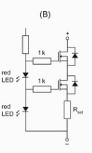
A better output section would allow you to tune each operating point current for each tube - also should one tube start arcing, it's not going to take out the other tubes. In the arcing scenario - the current of 3x has a low impedance path through the arc. In a open tube scenario, the two remaining triodes are now seen 3x current across the two tubes - overloading the tubes.

You can see that each tube has it's own CCS, and output cap bank onto the output. In your case each tube would have a 150uF+0.22uF cap.
That takes the Broskie circuit - the same can be done for 6as7s in parallel.
Last edited:
Thank you for the library!
Yes i have and i basically came to the conclusion that the 21th century maida controller would be my best bet in terms of space savings and performance. i know v3 of it is capable of handling 400mA so i would need two.
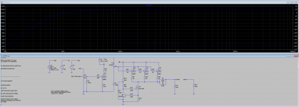
i will look in to going for individual CCS's for each tube, should be no problem to incorporate and i think it's what you said in an earlier post about the cascaded CCS.it's driven to the point of turning off the mosfet so i think if i go for something like this with two DN2540 i should be good.
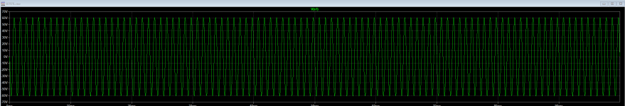
i must ask again because i find it very strange that i get +/-60Vpeaks (120Vpp) from a single 6SN7, is this even possible?
Have you considered you power supply?
Yes i have and i basically came to the conclusion that the 21th century maida controller would be my best bet in terms of space savings and performance. i know v3 of it is capable of handling 400mA so i would need two.
i will look in to going for individual CCS's for each tube, should be no problem to incorporate and i think it's what you said in an earlier post about the cascaded CCS.it's driven to the point of turning off the mosfet so i think if i go for something like this with two DN2540 i should be good.
i must ask again because i find it very strange that i get +/-60Vpeaks (120Vpp) from a single 6SN7, is this even possible?
Attachments
- Home
- Amplifiers
- Tubes / Valves
- Help wanted - SET OTL Headphone amp