Hi All,
I’m hoping to get some guidance/clarification on how to mount a woofer to make impedance/TS measurements.
I have read many write-ups on how to make the measurements but many of these don’t even mention how the driver should be mounted. For the ones that do mention mounting, there seems to be several camps: 1) Hang the driver in free air, 2) Rigidly mount the driver in mid air, 3) Place the driver on the magnet facing upwards (but that doesn’t seem right at all).
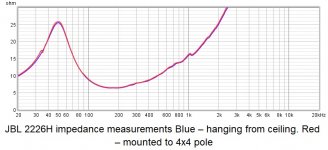
Hanging the driver from the ceiling is the easiest and I tried that first. I was measuring a 2226 woofer and the Fs peak was at 50 Hz when it should have be 40 Hz. So I thought that maybe the hanging approach wasn’t right. So I made a fixture to mount the driver off the corner of a 4x4 column in the basement. The resonant peak was still at 50 Hz but there was now a peak at 34 Hz which turned out to be the resonant frequency of the 4x4 column.
The REW help files for making TS measurements states “Note that the drive unit must be rigidly supported during the measurements, and ideally mounted vertically.“ This falls into camp #2 but I have yet to find anything on how to do this.
So does one need to make an elaborate stand to mount a driver to take these measurements or can the driver be hung from the ceiling using a coat hanger?
Thanks in advance
Bob
PS. I have to keep reminding myself that this is to try and figure out why the 2226 FS is coming in at 50 vs 40 Hz. (“When you are up to your ears in alligators, its hard to remember that your initial initiative was to drain the swamp!”)
PPS. If the driver does need to be rigidly mounted, recommendations would be greatly appreciated.
I’m hoping to get some guidance/clarification on how to mount a woofer to make impedance/TS measurements.
I have read many write-ups on how to make the measurements but many of these don’t even mention how the driver should be mounted. For the ones that do mention mounting, there seems to be several camps: 1) Hang the driver in free air, 2) Rigidly mount the driver in mid air, 3) Place the driver on the magnet facing upwards (but that doesn’t seem right at all).
Hanging the driver from the ceiling is the easiest and I tried that first. I was measuring a 2226 woofer and the Fs peak was at 50 Hz when it should have be 40 Hz. So I thought that maybe the hanging approach wasn’t right. So I made a fixture to mount the driver off the corner of a 4x4 column in the basement. The resonant peak was still at 50 Hz but there was now a peak at 34 Hz which turned out to be the resonant frequency of the 4x4 column.
The REW help files for making TS measurements states “Note that the drive unit must be rigidly supported during the measurements, and ideally mounted vertically.“ This falls into camp #2 but I have yet to find anything on how to do this.
So does one need to make an elaborate stand to mount a driver to take these measurements or can the driver be hung from the ceiling using a coat hanger?
Thanks in advance
Bob
PS. I have to keep reminding myself that this is to try and figure out why the 2226 FS is coming in at 50 vs 40 Hz. (“When you are up to your ears in alligators, its hard to remember that your initial initiative was to drain the swamp!”)
PPS. If the driver does need to be rigidly mounted, recommendations would be greatly appreciated.
Impedance measurement requires a driver to be vertically rigidly mounted in free space. This means a U frame placed far from floor, walls, ceiling and objects.
I don't have the space for this and my quick&dirt method is to "glue" a driver to a hard surface floor with some blu tack. If there is a vent in the magnet try to leave it free. This is usually enough for crossover simulation.
As to why your driver has a resonance at 50 Hz instead of the 40 Hz advertised: a new driver (or old but unused for a while) should be fully broken in before measurements in order to loosen the suspension. JBL states "Thiele/Small parameters are measured after 2 hour exercise period using a 600 W AES power test and will reflect the expected long term parameter values once the driver has been installed and operated for a short period of time"
Ralf
I´m using a wise mounted to an engine cart.
I clamp the magnet to the wise and that´s quite rigid.
I clamp the magnet to the wise and that´s quite rigid.
Suspending the driver in free air is good enough for TSP measurements. The air load (acoustic impedance) on the cone at fs is so low that fixing the driver doesn’t really add much. Your measurement differs from the data sheet? Welcome to the real world 😉
The air load (acoustic impedance) on the cone at fs is so low that fixing the driver doesn’t really add much.
Hanging the driver results in a resonance combination of moving diaphragm mass and reacting driver (magnet, basket) mass. Resulting resonance frequency will differ significatly from the "real" fs when driver is firmly mounted. Just try it!
Hanging the driver results in a resonance combination of moving diaphragm mass and reacting driver (magnet, basket) mass. Resulting resonance frequency will differ significatly from the "real" fs when driver is firmly mounted. Just try it!
Yes. One should try with a 21" thingy with 300-400g Mmd . . . And compare to rigid measurements.
To add: LEAP5 .ltd model is based on several impedance curves with different voltages. IE, one has to measure the Z with voltages that drive the transducer to linearity limits. +/- 10mm and 400g Mmd creates quite a force . . .
How significant? How far off would you be with a typical weight ratio of 1:20?Hanging the driver results in a resonance combination of moving diaphragm mass and reacting driver (magnet, basket) mass. Resulting resonance frequency will differ significatly from the "real" fs when driver is firmly mounted. Just try it!
How significant? How far off would you be with a typical weight ratio of 1:20?
I will have to dig through my harddrive for the measurements once i am back at the computer. Hope i kept the non-reliable "held by hand" results.
Not only was the resonance frequency different but also the impedance peak, so ts-parameters will not be reliable.
Measurements
I should have included these in the original post to avoid any confusion.
The blip at 34Hz in the red trace is the 4x4 post resonance. To me it would seem that there is no difference between hanging and hard mounting the driver.
I should have included these in the original post to avoid any confusion.
The blip at 34Hz in the red trace is the 4x4 post resonance. To me it would seem that there is no difference between hanging and hard mounting the driver.
Attachments
My 2ct
Without going into the calculations, we can assume the suspended measurement will show higher fs values. Because the frame plus magnet will move too, the virtual spring that couples the cone to a virtual inert point will be stiffer (k increases). But how much? Assuming a pretty linear spring (we are talking about small signal with TSP), the increase of k will be inverse to the shorter spring length. Which in it’s turn shortens by about the ratio of the cone mass divided by the total mass. Being some 5 percent in my example.
Now fs is determined by SQR(k/m) in a simple mass on a spring onedimensional system. So the new fs will be about 2,5% higher.
Real drivers however more likely have ratios cone mass to total mass of 1:100, so the difference will even be smaller (0,5%). Of course the shape of the impedance curve will change too, Rms doesn’t change whatever you do with the driver.
Compare this all to the huge changes in fs during operation (up to 20% change), I really don’t mind suspending the driver in free air. In fact, it would be more logical to advocate measuring in an infinite baffle. That would give a more realistic acoustic impedance than free air.
Would be great with some pictures of your methods. Most descriptions can be understood in several ways
Cheers!
Cheers!
Last edited:
Simply because I had free access to a metal fabrication shop with plenty of angle iron off cuts/scrap, I used a bolted together 1/4" x 2.5" x 4" angle iron constructed 'V' shaped vertical floor stand on industrial rollers; slid the driver down the 'V' till snug and quick clamped it in place, though made from construction lumber, carriage bolts/locking wingnuts if collapsing for storage is desired would work just as well with these or similar clamps:
locking wing nuts - Google Search
https://www.amazon.com/POWERTEC-203...la-760193875632&ref=&adgrpid=63364097444&th=1
locking wing nuts - Google Search
https://www.amazon.com/POWERTEC-203...la-760193875632&ref=&adgrpid=63364097444&th=1
More measurements
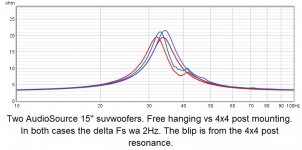
Thanks everyone for your inputs. I also have two AudioSource subwoofer drivers that I measured free hanging and mounts to the 4x4 column. For these, the resonance dropped about 2 Hz. See plots below. One thing that is very different with the AS drivers is that the basket is stamped sheet metal (vs cast aluminum on the JBL). When mounted to the pole, in only two places, there could be flexure at the mounting points.
Thanks everyone for your inputs. I also have two AudioSource subwoofer drivers that I measured free hanging and mounts to the 4x4 column. For these, the resonance dropped about 2 Hz. See plots below. One thing that is very different with the AS drivers is that the basket is stamped sheet metal (vs cast aluminum on the JBL). When mounted to the pole, in only two places, there could be flexure at the mounting points.
Attachments
Pole Mount
Below are some pictures showing one of the AudioSource drivers mounted.
Also shown is a driver hanging from the ceiling using a carefully crafted ceiling mount 😀


Below are some pictures showing one of the AudioSource drivers mounted.
Also shown is a driver hanging from the ceiling using a carefully crafted ceiling mount 😀
By guessing the cone mass you even could correct the free hanging measurement. In this case and put otherwise, my guess would be those woofers weigh about 3-4kg.assuming a cone weight of about 150-200g.
- Home
- Loudspeakers
- Multi-Way
- Woofer mounting to make impedance/TS measurements