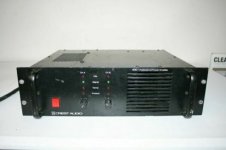
hi i bought a damaged crest 4001 amplifier

im new to repairing amps i have repaired already half a dozen
but this is my first profesional amp
so i already changed the damaged nec 2sb600/2sd555 https://www.diyaudio.com/forums/attachments/solid-state/998278d1637121923-crest-audio-4001-profesional-poer-amplifier-help-biasing-help-datasheet-2sb600-2sd555-nec-pdf outputs transistors for on-semi mj21195/mj21196 https://www.diyaudio.com/forums/attachments/solid-state/998279d1637121923-crest-audio-4001-profesional-poer-amplifier-help-biasing-help-datasheet-mj21195_on-pdf
changed all the capacitors, some damaged resistors, diodes, the damaged toshiba drivers 2sa10006/2sc2336 https://www.diyaudio.com/forums/attachments/solid-state/998280d1637121923-crest-audio-4001-profesional-poer-amplifier-help-biasing-help-datasheet-2sa1006-1006a-2sc2336-2336a-2336b-pdf for on-semi mje15032/mje15033 https://www.diyaudio.com/forums/attachments/solid-state/998281d1637121923-crest-audio-4001-profesional-poer-amplifier-help-biasing-help-datasheet-mje15032-pdf and a damaged mje340https://www.diyaudio.com/forums/attachments/solid-state/998282d1637121923-crest-audio-4001-profesional-poer-amplifier-help-biasing-help-datasheet-mje340-pdf for a new of the same
the amp is turning on the 3 relays click and i have output the thing is the biasing preset is turn all the way down its a 250ohm preset its my first to-3 transistor amp i fix and i cant place the probes easily as a to-222 transistor because of its design and i need help so where i can place the probes to calibrate bias and if i need to put a higer ohm preset
Attachments
-
 crest4001.jpg19.1 KB · Views: 1,222
 -
datasheet mje340-ON.pdf158.4 KB · Views: 158
-
datasheet MJE15032-ON.PDF219 KB · Views: 166
-
datasheet 2SA1006, 1006A,2SC2336,2336A,2336B.pdf191.2 KB · Views: 289
-
datasheet MJ21195_ON.pdf174.9 KB · Views: 133
-
datasheet 2SB600-2SD555-NEC.pdf87.5 KB · Views: 320
-
 IMG_20200115_005245.jpg600.3 KB · Views: 258
 -
 IMG_20200115_005328.jpg604.4 KB · Views: 304
 -
 IMG_20200109_150523.jpg721.4 KB · Views: 364
 -
 IMG_20200109_150501.jpg650.6 KB · Views: 409
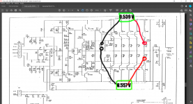
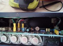
.You need to take the readings of both sides of the output transistor emitters to the center pin of R422. Maybe a better reference point would be emitter of q4 or q5.
The .557 volt to lower side R422 is 1.6 A which is way too high.
You may have to short a diode in the stack cr5-cr8 or reduce R15 resistor to get the idle current down to .02 A.
The .557 volt to lower side R422 is 1.6 A which is way too high.
You may have to short a diode in the stack cr5-cr8 or reduce R15 resistor to get the idle current down to .02 A.
Last edited:
or reduce R15 resistor to get the idle current down to .02 A.
Increase I think 🙂 You need the transistor to turn on harder to reduce the bias voltage across it.
Different semiconductors could well have slightly different forward voltages to the originals. I would just just increase the 100 ohm that is in series with the preset.
.You need to take the readings of both sides of the output transistor emitters to the center pin of R422. Maybe a better reference point would be emitter of q4 or q5.
The .557 volt to lower side R422 is 1.6 A which is way too high.
You may have to short a diode in the stack cr5-cr8 or reduce R15 resistor to get the idle current down to .02 A.
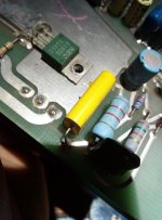
this is what i get
Attachments
Increase I think 🙂 You need the transistor to turn on harder to reduce the bias voltage across it.
i changed those and already check those for leaks so that isnt why
Different semiconductors could well have slightly different forward voltages to the originals. I would just just increase the 100 ohm that is in series with the preset.
what shold be a good R value for this?
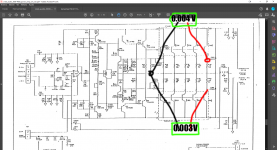
The emitters of the drivers Q9 and whatever the other one is in post 8 are the wrong places to measure output transistor idle current. The emitters of q4 & q5 are connected to the 422 you used to measure in post 6. That is the right reference point.
The readings in post 6 were not too bad. 9 ma bottom and 12 ma top. Was that with the 100 ohm R15 or the 470 ohm? If 470, just turn the pot up to get .006 or .008 volts or about .020 amps idle current. If the pot won't go high enough to back to 100 ohms or 220 which you could parallel with another 220 if it turns out to not give you the adjustment range you need.
The readings in post 6 were not too bad. 9 ma bottom and 12 ma top. Was that with the 100 ohm R15 or the 470 ohm? If 470, just turn the pot up to get .006 or .008 volts or about .020 amps idle current. If the pot won't go high enough to back to 100 ohms or 220 which you could parallel with another 220 if it turns out to not give you the adjustment range you need.
Last edited:
what shold be a good R value for this?
I'm looking a bit more closely at the circuit now and I've not fully appreciated how it worked at first. The component values seems a bit odd but I see now why.
So what indianajo said at first was correct (apologies indianajo).
I would say put the 100 ohm back in place and centre the preset. You may find reducing R6 (is it? blurry) and or R7 gets you in the target range. If not you would have to look at linking one of the diodes out.
I'm guessing the MJE is mounted on the heatsink to sense temperature and if so then it is important not to totally remove its function by having the preset on minimum resistance. That is why I would say set it midway at first and then try and get in range by fiddling the diode chain and resistors.
The readings in post 6 were not too bad. 9 ma bottom and 12 ma top. Was that with the 100 ohm R15 or the 470 ohm? If 470, just turn the pot up to get .006 or .008 volts or about .020 amps idle current. If the pot won't go high enough to back to 100 ohms or 220 which you could parallel with another 220 if it turns out to not give you the adjustment range you need.
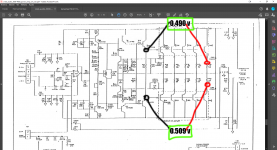
the img on post 6 are reading on the repaired channel i changed the resistor for a 430 ohm and now i can lower more the voltage to the levels of the other channel that wasnt blown up
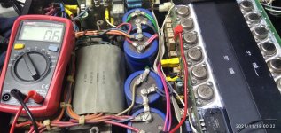
im runing it with a light bulb in series in the main power plug
the rails rigth now are +67 - 0 - 67 whitout the ligth bulb they go up to +92 0 -92
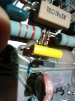
im measuring it like this now (see img)
if i turn it up more than 0.002 the ligth on the on switch goes off so i thing thats to high
Attachments
You may also have a DC out problem. Protection doesn't trip on too much idle bias current in the output transistors. It trips on too my dc out before the relay. Many amps also trip the protection for temperature sensors showing the heat sink is too hot. Sensors may be false reporting: you have to check it. Integration cap on the DC detect is often a trouble point. The are small and get leaky.
im so so so sorry
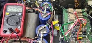
now i see why i couldnt belive the readings the multimeter has a MV scale on the selector i turned it to that scale and now i read 0.6 MV with the light bulb on series im sorry my bad
now i see why i couldnt belive the readings the multimeter has a MV scale on the selector i turned it to that scale and now i read 0.6 MV with the light bulb on series im sorry my bad
Attachments
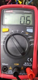
If you are measuring emitter voltage of an output transistor, you want 6 mv, not 0.6 mv. .006v/.33ohm=.019A or about right idle current for TO3 packaged output transistors.
0.6 mV *with* the light bulb in series is a good place to start. You want some room to be able to turn up when you run on full voltage. I usually run about 3mV with full line voltage, after some time idling.
There isn’t a *lot* of adjustment range on this, which is why it seems tricky setting it.
There isn’t a *lot* of adjustment range on this, which is why it seems tricky setting it.
8 ohm speaker?
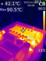
If the AC voltage out on speaker is 40 those temps are okay.
If it is 25 then those temps are high. More fan, Scotty. Halve that for 4 ohm speaker. Speaker impedance is usually 4/3 speaker resistance.
Note cheap DVM produce random numbers on music. I use a analog VOM to measure music. The $14 analog vom from the hardware store with a 50 vac scale are fine.
On a PA amp with 3 sets of initials on the heatsink, I decided the heatsink & fan were inadequate. Four output transistor meltdowns are too many. Unless the roadies were repeatedly tripping over the speaker cords and pulling the 1/4 phone plugs part way out, causing shorts. I drilled & tapped some #4 holes in the heatsink and added four TO3 heatsinks with the fins pointed up in the air. Used heatsink compound, too. If I lived in Europe or Asia I would use 3 mm screws.
Last edited:
Is that bridged 4 ohms, or 4 ohms per channel? If it’s 4 ohms per channel, you need more fan. 4 ohms per channel would be considered normal operation, and would need to tolerate that all night, as loud as one can stand to listen. Most amps, even the most expensive ones, will go into thermal protect at 4 ohms bridged if turned up to horrible amounts of distortion. But play fine if played “clean”.
- Home
- Amplifiers
- Solid State
- crest audio 4001 profesional power amplifier help biasing help