Hey all!
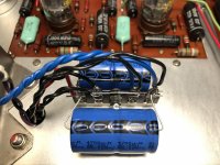
I've just removed the old selenium rectifier in my PAS 3. I've mounted a terminal strip with 2 new 4700uF capacitors and 2 1N007 diodes. I just want to check with the experts here if the positioning of the diodes are correct? The wiring is exactly like it was in stock form as well as the polarity of the caps. As I understand it I should remove the tubes from the line stage and phono board when firing it up and checking the voltages?
I've just removed the old selenium rectifier in my PAS 3. I've mounted a terminal strip with 2 new 4700uF capacitors and 2 1N007 diodes. I just want to check with the experts here if the positioning of the diodes are correct? The wiring is exactly like it was in stock form as well as the polarity of the caps. As I understand it I should remove the tubes from the line stage and phono board when firing it up and checking the voltages?
Attachments
Last edited:
I think you have some miswiring there, so DO NOT apply power.
The left (negative) end of the lower capacitor is wrongly connected to the leftmost terminal.
INSTEAD that negative end should be connected to the second to left terminal.
There may be other problems, but the photo is hard to see and trace.
After the wiring is corrected you can try measuring the output DC voltages.
The filaments of the tubes on each board are in series, so if the tubes are removed,
you will have to measure between the ends of each twisted pair where they are
soldered to the board. The DC voltage between the ends should be around 24VDC.
The polarity does not matter.
Last edited:
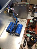
What's that red wire for? Did you compare to the schematic?
https://www.thetubestore.com/lib/th...aco/Dynaco-PAS-3X-Schematic-Owners-Manual.pdf
https://www.thetubestore.com/lib/th...aco/Dynaco-PAS-3X-Schematic-Owners-Manual.pdf
The red wire is one of the two wires in the twisted pair from either the line stage or the phono stage.
Have to see the other end of the wire to know which stage.
Have to see the other end of the wire to know which stage.
I think you have some miswiring there, so DO NOT apply power.
The left (negative) end of the lower capacitor is wrongly connected to the leftmost terminal.
INSTEAD that negative end should be connected to the second to left terminal.
There may be other problems, but the photo is hard to see and trace.
After the wiring is corrected you can try measuring the output DC voltages.
The filaments of the tubes on each board are in series, so if the tubes are removed,
you will have to measure between the ends of each twisted pair where they are
soldered to the board. The DC voltage between the ends should be around 24VDC.
The polarity does not matter.
Gah, I can't comprehend how I managed to mount it on the wrong terminal. I draw a simple schematic which was right but still managed to mount it wrong. Thanks for the heads up! I know all the wiring is at the same terminals as it was originally, I put tape on all of them with numbers ranging from 1-4. 1 being the leftmost terminal and 4 being the right.
Thanks for the help and I'll post some more pictures tonight with detailed description of the wiring.
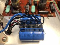
So I've switched position of the left leg (negative) of the closest capacitor to terminal 2.
It was easy replacing the selenium rectifier with the terminal strip, but not as easy removing it and rearranging the leg orientation. I must also say that it was extremely hard getting solder to wet properly on the terminal strip I got from Mouser. It works now but it's not pretty..
Oh well, I've traced the wiring and all seems correct according to the manual.
-Red wire goes from eyelet 15 on phono board to terminal 1.
-Black wire goes from eyelet 14 on phono board to terminal 2.
-Black wire goes from eyelet 18 on line board to terminal 1.
-Black wire goes from eyelet 19 on line board to terminal 2.
-Black twisted pair from rectifier tube goes to terminal 3 and 4.
-Blue twisted pair from transformer goes to terminal 3 and 4.
So capacitor orientation is correct now, and as I understand it diode orientation and placement as well..?
Attachments
Last edited:
I have done a similar swap in a pair of Tandberg taperecorders. There could be an issue with increased B+ due to more efficient diodes than the selenium rectifier. With the Tandbergs, they had a 245VAC operation tap on the power transformer, so I was abe to use that to lower some B+, and then I fitted a NTC (CL-90 I think) that softened the startup, and was introducing a small voltage drop of its own. In the end I still had a few extra volts of B+, but it was within tolerance. The heaters were marginally below the 6.3V due to the use fo the higher voltage tap on the PT, so probably helping the life of the tubes a bit.
Maybe I'm missing something, but aren't those electrolytics just 40VDC rated? Is this some other rail that is being rectified, and not B+?
Maybe I'm missing something, but aren't those electrolytics just 40VDC rated? Is this some other rail that is being rectified, and not B+?
Last edited:
See the schematic in post #3. It's a voltage doubler/dc supply for the filaments, other than that of the rectifier.
So capacitor orientation is correct now, and as I understand it diode orientation and placement as well..?
Seems ok.
Seems ok.
Fired it up tonight, it works. The heater is exactly 24 DCV now. Thanks for all the help Rayma!
Sure, this is the first upgrade needed in the PAS. If you want to do anything else, ask me first.
Sure, this is the first upgrade needed in the PAS. If you want to do anything else, ask me first.
Thanks, I’ll be in touch!
- Home
- Amplifiers
- Tubes / Valves
- Dynaco PAS 3 selenium rectifier replacement.