I have read the sticky on crossover design. I've been reading the 6HX150 thread (nice cabinets!) and some other XSIM threads but need specific help with my design.
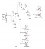
I have been eyeballing the 6HX150 for a center channel and was thinking of flanking it with four Dayton Audio RS150T's. Dimensions could be roughly 75" wide x 7" tall x 5-6" deep. I would also like to build/buy L&R to have matching LCRs. Here's a draft of my XO but the curves look like crap...see image attached.
I have been eyeballing the 6HX150 for a center channel and was thinking of flanking it with four Dayton Audio RS150T's. Dimensions could be roughly 75" wide x 7" tall x 5-6" deep. I would also like to build/buy L&R to have matching LCRs. Here's a draft of my XO but the curves look like crap...see image attached.
Attachments
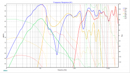
Notice here that there are four response curves, the tweeter, the mid, one woofer, and the total (system). There are three phase curves.
Begin by getting one of the two crossovers close. For this, say you choose to begin with the lower cross. Enable the system response. Disable the system phase. Enable the mid response. Enable a woofer response. Disable the tweeter plots. Disconnect the tweeter completely on the schematic so it doesn't affect the total. Enable the woofer and mid phase plots. Set the system response toward the top of the plot and make the range roughly 40dB. Set the frequency range.
Then change to the upper crossover. Leave the woofers connected and reconnect the tweeter on the schematic. Disable the woofer phase and enable the tweeter phase and response.
Attachments
I will give it a shot and post my results. I started with the crossover for the coax and it looked pretty good until I added the rest. All four subs had identical curves so I only show the one. I forgot to flip the phase of my tweeter. I appreciate the advice!
Begin by getting one of the two crossovers close. For this, say you choose to begin with the lower cross. Enable the system response. Disable the system phase. Enable the mid response. Enable a woofer response. Disable the tweeter plots. Disconnect the tweeter completely on the schematic so it doesn't affect the total. Enable the woofer and mid phase plots. Set the system response toward the top of the plot and make the range roughly 40dB. Set the frequency range.
I turned on/off the curves you suggested and changed my ranges. Disconnected the tweeter. Focussed FR from 80-2k since the tweeter comes in at 1700 and my subs will play from about 100Hz down. Here is my work on the woofer-mid.
I had to invert the phase on the mid to alleviate the dip in the system FR. Is that the best approach?
I also removed the added 6dB sensitivity I had on the woofers which made the system curve look better. I'm not sure if that sensitivity needs to be boosted by 6dB because of the multiple woofers or if the software accounts for that?
My initial design erroneously said 455Hz but should've said 425Hz. I also chose 255Hz. What is the better choice?
new .dxo attached. Thanks for the review!!!
Attachments
Inverting the polarity was a good choice.
The simplest way to do the woofer is to disconnect three of them and increase the remaining one by 6dB. This way the impedance and sensitivity will be as for four of them.
Where did you get your measurements and have you considered the effects of the baffle?
The simplest way to do the woofer is to disconnect three of them and increase the remaining one by 6dB. This way the impedance and sensitivity will be as for four of them.
Where did you get your measurements and have you considered the effects of the baffle?
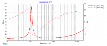
The response curve of the mid cone looks suspect to me: what's with the 150Hz spike?
Might be worth putting an LCR filter across it to flatten the impedance peak at resonance (the likely cause), or move the crossover up into the 3-500Hz area.
Chris
Might be worth putting an LCR filter across it to flatten the impedance peak at resonance (the likely cause), or move the crossover up into the 3-500Hz area.
Chris
Inverting the polarity was a good choice.
The simplest way to do the woofer is to disconnect three of them and increase the remaining one by 6dB. This way the impedance and sensitivity will be as for four of them.
Where did you get your measurements and have you considered the effects of the baffle?
Ok, 1 woofer at +6dB. Measurements came from Parts Express on the woofer and dibirama for the FaitalPro (I couldn't find files for that anywhere else - lots of popular links didn't work for me). I have only briefly read and been warned of baffle step. Not sure I fully understand the phenomenon.
@chris661 I think the spike at 150 is the woofer not the mid... I've been mostly focused on the design using the 425Hz xo point.
I'm mentioning items, sometimes they're interdependent and ignoring them might have knock on effects.
The midrange impedance is 'interesting'. I'd be inclined to use a filter to knock down the peak, however this depends on checking it is correct.
Furthermore, it depends on the box you use. This should be measured but it could be simulated.
There are a bunch of ways to get there but I'm guessing if I don't know what you can do. It could be calculated before you trial an actual crossover, or estimated and then you measure the real impedance with crossover and tune it later. In any case this is the thing with sharp filters, they need to be on point.
Attachments
- Home
- Loudspeakers
- Multi-Way
- Need help with my center channel design!!! Rookie at XSim