How important is uniform distortion across whole audio bandwidth?
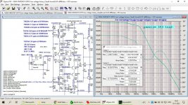
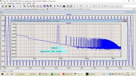
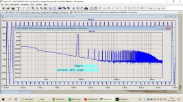
I simulated two cases of the same CFA, first one with passively loaded IPS and second one with actively loaded IPS.
First one have almost equal distortion over whole audio bandwidth and second one is with very low distortion until 1 kHz (simulation shows almost zero distortion) and gradually increasing after that.
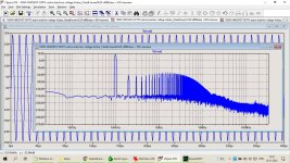
Harmonic profiles showed for 8 kHz (I chose that frequency because second harmonic falls in audio band) are bit different but still look benign for both of the cases.
It is quite simple to make Loop Gain for active loaded IPS flat up to 20 kHz introducing or local FB or VAS load. Is that better way or just live it as it is with very low distortion up to 1 kHz and increase after that.
Damir
I simulated two cases of the same CFA, first one with passively loaded IPS and second one with actively loaded IPS.
First one have almost equal distortion over whole audio bandwidth and second one is with very low distortion until 1 kHz (simulation shows almost zero distortion) and gradually increasing after that.
Harmonic profiles showed for 8 kHz (I chose that frequency because second harmonic falls in audio band) are bit different but still look benign for both of the cases.
It is quite simple to make Loop Gain for active loaded IPS flat up to 20 kHz introducing or local FB or VAS load. Is that better way or just live it as it is with very low distortion up to 1 kHz and increase after that.
Damir
Attachments

Bruno Putzeys says: If distortion is safely inaudible in the whole audio bandwidth, it does not matter much (just make sure things don't start misbehaving badly in the ultrasonic range). If not, flat is preferred.
These two circuits seem to be basically equivalent, but keep in mind that the active load circuit would also have better low-frequency PSRR with its higher loop gain down there. You have to decide whether that's worth it to you. Loop gain topping out below 80 dB isn't all that great though.
BTW, 1n5 is rather a lot of input capacitance.
I use, in my setups, a preamps with very low output impedance, and prefer low value for the input resistor to lower input distortion caused by nonlinear base current. If used a preamp with higher output impedance it's easy to decrease that cap. Any how this type of IPS has kind of input base current cancelation.
attached Close Loop Gain
attached Close Loop Gain
Attachments
It comes down to the designer's philosophy on area of focus. There is a clear difference between your examples in out-of-band performance. Namely the minimum phase margin. Many amplifiers' distortion performance collapses out of band. A distortion test I run is 100KHz/200KHz into capacitive load. This gives information about the design retaining control. My personal preference is to check the entire bandwidth such that distortion does not get worse than 'x' by the time -3dB is reached. This approach is more industrial than normally pursued for audio.
My version would engineer a flat out of band phase, rather than a saddle for the reasons above.
My version would engineer a flat out of band phase, rather than a saddle for the reasons above.
How important is uniform distortion across whole audio bandwidth? Damir
Not important at all.
Glad to see this topic. Compare a old Rotel with a Parasound. Dominant pole compensation vs Miller.
All things equal, DPC is higher at low frequencies, but reduces as freq increases. Miller is lower across the audio band, but remains level. This matters with less than perfect tweeters. Where a DPC amp may not produce the high frequency harmonics that excite tweeter breakup, a Miller amp may, but with good tweeters, the Miller compensation really opens up the details. This is a case where a smart engineer chooses the best topology for the intended use. Bill ( I think) at Rotel built amps for the upper mid-fi market, so chose DPC. John assumed the best speakers possible and chose Miller. Both correct, both understood their market. Erno chose DPC for the MOSFET amps as he knew it was almost impossible to get stability with Miller using MOSFETS. All smart guys.
All things equal, DPC is higher at low frequencies, but reduces as freq increases. Miller is lower across the audio band, but remains level. This matters with less than perfect tweeters. Where a DPC amp may not produce the high frequency harmonics that excite tweeter breakup, a Miller amp may, but with good tweeters, the Miller compensation really opens up the details. This is a case where a smart engineer chooses the best topology for the intended use. Bill ( I think) at Rotel built amps for the upper mid-fi market, so chose DPC. John assumed the best speakers possible and chose Miller. Both correct, both understood their market. Erno chose DPC for the MOSFET amps as he knew it was almost impossible to get stability with Miller using MOSFETS. All smart guys.
he knew it was almost impossible to get stability with Miller using MOSFETS
Wherever did you get this idea? It is completely false.
Guess you never tried it. Why don't you do a SPICE model and look at the issues for yourself. I did. I eventually succeeded, but the slightest variance if tolerances would cause it to oscillate. The very wide bandwidth means the phase margin is very small.
I was given that information by another well known designer who knew him.
I was given that information by another well known designer who knew him.
Here is not question about compensation. This is the same amp with the same type of compensaion (OITPC - Output Inclusive Two Pole Compensation) but one with resistive (passive) loaded IPS and other with active (CM) loaded IPS and in that way getting different Loop Gain, consequently different level and shape of THD over audio band.
consequently different level and shape of THD over audio band.
I think the priority of lower THD or harmonic profile or almost same THD at audio band is different for everyone. You should build them yourself and compare them in the listening test.
For many people, it is difficult to know distortion at high frequency because they use low quality of speaker. In my country, my amplifier with bootstraped VAS is more popular for use in live music because they use cheap speaker. My amplifier have THD not very low but dominant H2, so cheap speaker sound more pleasing.
If I use high quality speaker, I prefer monotonic harmonic profile first, and second is almost same THD at audio band, and third is lower THD.
I think it´s a non issue.
When you sweep a sinewave 20Hz to 20kHZ you may get different THD "numbers" at different frequencies, which can be boiled down to nonlinearities there, but with any complex program (a.k.a. "Music") any non linearity will affect ALL frequencies present, causing intermodulation, besides plain harmonic distortion.
In case it´s not clear: even frequencies outside the "problem band" will be affected.
So worrying only about the latter and only at certain frequencies means nothing.
I think it´s a non issue.
So worrying only about the latter and only at certain frequencies means nothing.
Who is talking about certain frequencies, it was question about whole audio band distortion, even outside it.
Simulation at 8 kHz is showing harmonic profile for different IPS load.
I think the priority of lower THD or harmonic profile or almost same THD at audio band is different for everyone. You should build them yourself and compare them in the listening test.
It's easy to say do listening test by yourself, in most cases it's just subjective opinion.
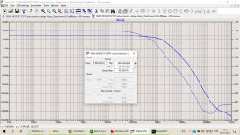
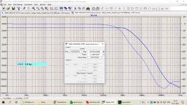
The closed loop phase response of both of these amplifiers is exemplary - I can’t zoom in , but my guess is it’s less than 1-2 degrees at 20 kHz.
The loop response I’d a different thing, and there you get the typical saddle arising from TPC or TMC. I don’t think this has any baring on ‘sound quality (ok, that’s my opinion 🙂 )
Re closed loop phase response, people agonize over it in power amps when the electro-acoustic part of the chain (recording side and pickup cart if you are using vinyl) and then the speaker side is spread over orders of magnitude more than an amplifier.
Basically, it’s a non-issue IMV.
It's easy to say do listening test by yourself, in most cases it's just subjective opinion.
It is subjective. Because amplifier is not ideal, so we must make the priority which is more important and which is less important. If you can made ideal amplifier, you will not consider those things.
The closed loop phase response of both of these amplifiers is exemplary - I can’t zoom in , but my guess is it’s less than 1-2 degrees at 20 kHz.
CLG plot of an amp with TPC or TMC has typical increase in high frequency, in this case at cca 1 MHz and phase response at 20 kHz is defined solely by input filter.
attached CLG plot with no input filter.
PS why you can't zoom in?
Attachments

I meant trying to see the exact phase lag at 20 kHz - I think its 1-2 deg? you cant tell from the plot. In any event, its nothing to worry about IMV 🙂
- Home
- Amplifiers
- Solid State
- Importance of uniform THD in whole audio bandwidth