Alright, I'm just about to take delivery of my power transformers so it is about time to heat up the ol' iron and start putting this design together. Apart from doing the calculations on a piece of paper using a freshly sharpened pencil I've simulated pretty much every aspect of this design and by the looks of it she should work.
However I'm a mere human, so I err every now and then, or make (in hindsight) dumb design choices, so I would appreciate an extra pair of eyes check this design over before I dim the lights on the whole street when I flip the power switch. Comments and suggestions are welcome, lets hear it gentlemen! Thanks! 😀
However I'm a mere human, so I err every now and then, or make (in hindsight) dumb design choices, so I would appreciate an extra pair of eyes check this design over before I dim the lights on the whole street when I flip the power switch. Comments and suggestions are welcome, lets hear it gentlemen! Thanks! 😀
Attachments
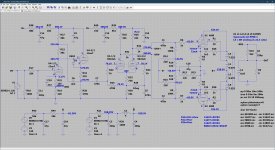
U4 ( the cathode follower) must have elevated filament to prevent breakdown filament<>cathode. 270Volt is way to much.
You could use one tube for both channel as cathode followers and elevate filement for those only.
Or, just skip the cathode follower, the following load is small.
You could use one tube for both channel as cathode followers and elevate filement for those only.
Or, just skip the cathode follower, the following load is small.
Last edited:
@petertub,
Ah yes, good catch, thanks! Maximum heater-cathode voltage is 100V on the 12AX7 so I'm certainly going to need to elevate the heaters. I was kind of fond of the cathode follower arrangement though as it allows for bootstrapping which really helps to reduce THD and further linearizes the amplifier.
Ah yes, good catch, thanks! Maximum heater-cathode voltage is 100V on the 12AX7 so I'm certainly going to need to elevate the heaters. I was kind of fond of the cathode follower arrangement though as it allows for bootstrapping which really helps to reduce THD and further linearizes the amplifier.
I’m not used to seeing a cathode follower (U4 2/2) before the phase inverter - are these amps to be build as monoblocks and you had an extra triode? Or do your simulations show an advantage to using it? What is the advantage?
Something seems off with the voltage between R9,R11.
Something seems off with the voltage between R9,R11.
Last edited:
I’m not used to seeing a cathode follower (U4 2/2) before the phase inverter - are these amps to be build as monoblocks and you had an extra triode? Or do your simulations show an advantage to using it? What is the advantage?
Something seems off with the voltage between R9,R11.
Ah yes, that's a wrong label attached to that node in the schematic, my mistake, that voltage is the same as for the other KT88. And I'll build monoblocks indeed, so might have to use a single triode instead. I'm currently recalculating the input stage to see if I can get equal performance at a lower voltage so I can get away with not having to lift the heater.
If you use a single triode for the first tube (VA) you might consider something like E86C. Or are you determined to use only tube that are currently being made?
If you use a single triode for the first tube (VA) you might consider something like E86C. Or are you determined to use only tube that are currently being made?
I have a large collection of tubes I'd like to use, most of which are commonly available. A D3A (triode mode) or a E80F/EF86 (triode) are also options, but welcome to suggestions, I m not familiar with the E86C?
U4 ( the cathode follower) must have elevated filament to prevent breakdown filament<>cathode. 270Volt is way to much.
I just wanted to make sure so I just checked three datasheets for the Sovtek 12AX7 LPS, the EH 12AX7 and the Tung-Sol 12AX7 and they specify 200V, 200V and 180V respectively, so I might get away with just selecting a different operating point of the first triode of the 12AX7? If I stick to a Va of say 150V I should be alright?
I do not think so.I just wanted to make sure so I just checked three datasheets for the Sovtek 12AX7 LPS, the EH 12AX7 and the Tung-Sol 12AX7 and they specify 200V, 200V and 180V respectively, so I might get away with just selecting a different operating point of the first triode of the 12AX7? If I stick to a Va of say 150V I should be alright?
That some vendors specify higher limits won't help future users who replaces
a 12ax7 thinking that any 12ax7 would do. When time has come to replace this tube you might not even have a vendor that makes tubes with this spec.
If you have an extra 6volt ( or 12 volt) winding it's an easy solution. If not maybe
you should redesign ..
When it comes to layout I would leave yourself the option of returning global NFB to the phase inverter instead of the input stage. This will give you an easy get-out-of-jail if you encounter any stability problem, and leave you with the option of tube rolling the input tube independently of gNFB.
I do not think so.
Well, don't take my word for it, the datasheets however don't lie, please have a look:
Sovtek 12AX7 LPS > specifies max. 200V for HC voltage.
https://www.thetubestore.com/lib/thetubestore/sovtek-12ax7lps.pdf
EH 12AX7 > specifies max. 200V HC voltage.
https://www.thetubestore.com/lib/thetubestore/eh-12ax7eh.pdf
Tung-Sol 12 AX7 > specifies max. 180V HC voltage.
https://www.thetubestore.com/lib/thetubestore/tungsol-12ax7.pdf
JJ 12AX7 > specifies max. 180V HC voltage.
https://www.thetubestore.com/lib/thetubestore/JJ-E83CC.pdf
When it comes to layout I would leave yourself the option of returning global NFB to the phase inverter instead of the input stage. This will give you an easy get-out-of-jail if you encounter any stability problem, and leave you with the option of tube rolling the input tube independently of gNFB.
Thanks! I didn't think of that, that's something to consider indeed.
I would not build anything that is on the limit of this spec. Staying inWell, don't take my word for it, the datasheets however don't lie, please have a look:
Sovtek 12AX7 LPS > specifies max. 200V for HC voltage.
https://www.thetubestore.com/lib/thetubestore/sovtek-12ax7lps.pdf
EH 12AX7 > specifies max. 200V HC voltage.
https://www.thetubestore.com/lib/thetubestore/eh-12ax7eh.pdf
Tung-Sol 12 AX7 > specifies max. 180V HC voltage.
https://www.thetubestore.com/lib/thetubestore/tungsol-12ax7.pdf
JJ 12AX7 > specifies max. 180V HC voltage.
https://www.thetubestore.com/lib/thetubestore/JJ-E83CC.pdf
the safe side ( < 100Volt) stresses the tube less and will stay clear of trouble.
I m not familiar with the E86C?
E86C is a special quality tube, but EC86 has identical specs. Very linear, mutual conductance=14 mA/V, Gain=68.
There you go: https://frank.pocnet.net/sheets/009/e/E86C.pdf
I would not build anything that is on the limit of this spec. Staying in
the safe side ( < 100Volt) stresses the tube less and will stay clear of trouble.
Oh absolutely, I’m very appreciative of your input, I’m definitely going to recalculate a different bias point for the input tube so the cathode follower sees about 100V or less on its cathode.
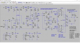
Gentlemen, please accept my apologies and disregard my previous flight of fancy .. err folly, hallelujah I have seen the light! By replacing the input section with a single EF86 everything falls into place, and yes, I know the EF86 has been around since the fifties, but my judgement was clouded and my vision impaired by the whispers of false gods sporting a cathode, anode and a single grid. Please find the latest draft schematic below, comments and suggestions are once more welcome!
Attachments
Last edited:
Very nice.
It's close to the Allen Organ 75 but with other tube types.
But they DC the EF86 with the splitter, so eliminating one coupling cap.
It's close to the Allen Organ 75 but with other tube types.
But they DC the EF86 with the splitter, so eliminating one coupling cap.
Consider triode strapping the EF86. There is a good amount of open loop gain in your current design, and unless you are going to apply a hefty amount of feedback, you could have an amp that is quite sensitive. That is unless you are going to drive it directly from a line source with a volume attenuator built in.
Huge H-K voltage is a tradition for 12AX7. An early use was operational amplifiers on +/-250V or +/-300V rails. In an analog computer the inputs and outputs can sit at any possible voltage for any length of time, even overnight (it reduces offset nulling). While the "legal limits" for good accuracy were +/-100V, simulations were unpredictable (if they were easily predictable, we would not need analog computers) so 150V and even 200V could happen.
Then we have some of the early McIntosh amplifiers with 12AX7 cathode followers bootstrapped off a 400V power stage. They could sit with most of 400V (on a nominal 330V bottle) and swing nearly 200V above and below ground.
Fender 5F6a *and many copycats* set the tone driver cathode above 200V. Yes, these do fail a bit more than other spots in the amp, but not enough to bother paying-gig musicians.
- Home
- Amplifiers
- Tubes / Valves
- Sanity check: KT88 PP design