I have a Citation 12 here, courtesy of a friend. I've been looking over the design and contemplating the Pass/MF12 redo. My desire to look before I leap won out and I started checking values on the stock chassis with a DMM and just doing a visual once-over.
When I flipped that chassis to look at the point-to-point wiring underneath I saw that each input had an axial cap in series, a 250uF/15v electrolytic. Testing showed these caps were far out of spec, with both of them around 330uF. One had an ESR in excess of 2 ohms.
I've never seen caps installed in series on inputs before now. Nelson's schematic for the MF12 showed a more traditional arrangement with a cap and resistor in parallel with signal and ground.
What is the purpose of these caps?
Forgetting about the MF12 project for now, if the amp goes back into service in stock condition, should those caps be replaced, or can they be eliminated in favor of a more traditional arrangement?
They are standard DC blocking input caps. However, they are much higher than anyone would ever need. If we assume that we see about 30K looking into R702, then putting the input -3 dB corner at 2 Hz would result in needing input caps of about 1/(2*pi*2*30000)=2.65 uF.
OK...bump it up a bit to 2.7 uF...and you can probably replace the original C1 with a very nice 2.7 uF film cap.
OK...bump it up a bit to 2.7 uF...and you can probably replace the original C1 with a very nice 2.7 uF film cap.
Electrolytic caps aren't known for tight tolerances. Take the highly regarded Silk 2 caps they are rated to be + & - 20% of the rated value and years ago most electrolytes weren't anything close to that usually rated at - 20% to + 80% so by the older standards yours caps were well within tolerances.
Agree, within tolerance for a large electrolytic, also 2 ohm ESR in series with a 30k input again is nothing.
That said, they impress me as being way too large and above suggestion of something between 2.5 and 3uF looks way more reasonable.
Applying any DC from a previous stage to original ones will allow a large thump through, with no improvement to audio quality.
That said, they impress me as being way too large and above suggestion of something between 2.5 and 3uF looks way more reasonable.
Applying any DC from a previous stage to original ones will allow a large thump through, with no improvement to audio quality.
They are standard DC blocking input caps. However, they are much higher than anyone would ever need. If we assume that we see about 30K looking into R702, then putting the input -3 dB corner at 2 Hz would result in needing input caps of about 1/(2*pi*2*30000)=2.65 uF.
Agree, within tolerance for a large electrolytic, also 2 ohm ESR in series with a 30k input again is nothing.
Here's the learning portion of today's episode - R702 is 2.7k, where is the 30k value coming from?
Please post the Schematic YOU are using here, different versions carry different parts designations.
Doubly so if we are not talking about Factory schematics but Mods.
Hardly any "learning" possible if we are talking about different stuff; "R702" by itself means nothing.
FWIW the schematics I saw never went above R19, go figure.
Doubly so if we are not talking about Factory schematics but Mods.
Hardly any "learning" possible if we are talking about different stuff; "R702" by itself means nothing.
FWIW the schematics I saw never went above R19, go figure.
I've never seen caps installed in series on inputs before now. Nelson's schematic for the MF12 showed
a more traditional arrangement with a cap and resistor in parallel with signal and ground.
The Citation 12 has a bipolar input stage. There is DC input current flowing, and there is a small DC voltage
across the 33k resistor to ground. This requires an input DC blocking capacitor, and is normal for this type
of input stage. It is best to use a nonpolar film or a bipolar electrolytic capacitor of 3uF to 10uF here.
It’s not uncommon for electrolytic capacitors to increase in capacitance over time/use.
Yesterday I replaced some in a crossover that had doubled.
Yesterday I replaced some in a crossover that had doubled.
Please post the Schematic YOU are using here, different versions carry different parts designations.
Doubly so if we are not talking about Factory schematics but Mods.
Hardly any "learning" possible if we are talking about different stuff; "R702" by itself means nothing.
FWIW the schematics I saw never went above R19, go figure.
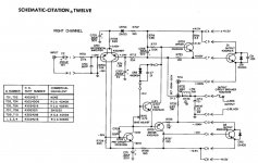
I wasn't the one who brought up R702, it was djoffe, I was simply quoting him. Looking at the schematic for the Citation 12, he's referring to the resistor before the rolloff network that precedes the differential pair.
Attachments
The Citation 12 has a bipolar input stage. There is DC input current flowing, and there is a small DC voltage
across the 33k resistor to ground. This requires an input DC blocking capacitor, and is normal for this type
of input stage. It is best to use a nonpolar film or a bipolar electrolytic capacitor of 3uF to 10uF here.
I have quite a few amplifiers here that also have bipolar inputs, yet none of them have a cap in series with the input. They do all have a resistor in parallel with a small capacitor. What is different about this amplifier that would require it to have this capacitor in series?
Nothing, all bipolar input amplifiers should have a DC blocking capacitor, even Ampzilla.
https://www.updatemydynaco.com/HistoricDocuments/ampzilla_web.pdf
Of course, fet input amplifiers without a DC blocking capacitor can have their DC operating points
disturbed by DC in the source.
The shunt capacitor low pass input filter is just to reduce out of band noise from entering the amplifier.
It doesn't affect stability since it is not within the nfb loop.
Last edited:
Nothing, all bipolar input amplifiers should have a DC blocking capacitor, even Ampzilla.
https://www.updatemydynaco.com/HistoricDocuments/ampzilla_web.pdf
Of course, fet input amplifiers without a DC blocking capacitor can have their DC operating points
disturbed by DC in the source.
The shunt capacitor low pass input filter is just to reduce out of band noise from entering the amplifier.
It doesn't affect stability since it is not within the nfb loop.
When you mentioned Ampzilla I started looking into more of Bongiorno's work. I found the Andromeda schematic on HiFiEngine and saw that he actually had two caps in series on his inputs; both were 330uF polar electrolytics and they were installed in opposition to each other - the negative leads were joined. WTH?
Looking at some of the Nelson Pass Adcom designs... the 555 did not have a DC blocking capacitorIf I look at amps that didn't have his mind behind it, such as the 565, I see a 4.7uF cap at the input, but the 535 and 545 didn't.
In your opinion, if an amplifier doesn't have the DC blocking input capacitor, can the amplifier be helped (either objectively or subjectively) by adding one?
And again, WTH is that opposing-polarity input capacitor thing on the Andromeda?
Thanks.I wasn't the one who brought up R702, it was djoffe, I was simply quoting him. Looking at the schematic for the Citation 12, he's referring to the resistor before the rolloff network that precedes the differential pair.
Personally fully agree with:What is different about this amplifier that would require it to have this capacitor in series?
,all bipolar input amplifiers should have a DC blocking capacitor,
in fact extend that to ALL amps; no speaker I know of can reproduce DC, so .....
Only needed in DC Servo Lab/Industrial amps, not the case here.
As of
check 33k R703Here's the learning portion of today's episode - R702 is 2.7k, where is the 30k value coming from?
Nit picking, full value is 33k in series with 2k7 with actual "transistor" Z in parallel, but calling it "30k" is close enough .
As of using HUGE C2 250uF there I think it´s conceptual error.
Clearly they are trying to match C707 , alson 250uF , but the impedance "seen" by those caps is absolutely different.
Input one C702 "sees" (is loaded with) 33k+2k7.
NFB C707 is part of a voltage divider R713 - R711 and the relevant value to calculate turnover frequency is just R711: 1k8
In which case that NFB net has a lower limit of: 0.35Hz
And why 0.35Hz and not, say, 2 Hz or 15 Hz?
Because here that cap is NOT to determine frequency response at all (it´s not considered good practice), and to boot , it being a POLARIZED electrolytic, we do NOT want to drop any significant voltage across it.
It only needs to stand a few mV amp offset, which to boot are predictable: I expect a small positive voltage there (PNP input transistors) , in fact schematic shows +40mV (a typical value) , so capacitor can be oriented accordingly.
But 250uF in series with input is nonsense.
It turns 2 polarized ones into a single Bi/Non polar one of half the capacity and same voltage handling.WTH is that opposing-polarity input capacitor thing on the Andromeda?
Today you can order any value; way back then sometimes you had to improvise.
And non polar is the key here, you do not know beforehand what kind of DC leak or offset could the driving preamp show at its output.
Last edited:
Yes, the two polar electroytics in anti-series not only become bipolar/nonpolar,
but also the composite capacitor has lower distortion than just one.
but also the composite capacitor has lower distortion than just one.
There's an argument for saying these can: What is A Rotary Subwoofer (Propeller Subwoofer)? | BoomSpeaker 🙂no speaker I know of can reproduce DC
Yes there are DC speakers but not in my house.
The resistor here sees 2.7k+33k||Z(Q1b) but we want to figure "very low F" so pencil 30k. For Hi-Fi that suggests a couple of uFd. Couple-uFd film caps can be large and costly. Many experimenters and authors suggest that making an electrolytic 10X or better 100X as big as "needed" will dilute the distortion to very-small. Which does suggest 200 or 400uFd, where bigger is better as long as physical size is not obnoxious (captures radio waves etc).
Simple electrolytics are polar. Reverse voltage will break through. 1V won't, so we sometimes see polar e-caps in bipolar jobs in low-level mike amps. Two caps back to back will also block DC both ways.
Actually, folks, there is a reason for a large input capacitor!
Some time ago I posted that turn-on thumps can be reduced if the input impedances on each side of a diff pair are properly balanced. That means there should be equal capacitances on the feedback decoupling as on the input. Ans there should also be equal resistances, which means if you follow this argument, the input resistor should balance the feedback "grounding" resistor - which is to say 1.8k, not 2.7k.
So it is not perfectly balanced (and anyway, in this case the simple resistor current source in the diff pair might cause as much turn on thump - it looks based on an old RCA "standard" quasi design.
Actually, folks, there is a reason for a large input capacitor!
Some time ago I posted that turn-on thumps can be reduced if the input impedances on each side of a diff pair are properly balanced. That means there should be equal capacitances on the feedback decoupling as on the input. Ans there should also be equal resistances, which means if you follow this argument, the input resistor should balance the feedback "grounding" resistor - which is to say 1.8k, not 2.7k.
So it is not perfectly balanced (and anyway, in this case the simple resistor current source in the diff pair might cause as much turn on thump - it looks based on an old RCA "standard" quasi design.
Interesting.
If you don't mind a rookie question - why is the large cap in series with the input side, but on the feedback side of the pair its headed to ground? If its blocking DC at the input, what is it doing on the other side?
the cap in the feedback allows unit feedback at DC, which minimizes the offset voltage that appears at the output of the amp.
the Citation 12 in stock form has always been noted for a "Pop" on turn-on...Why so? Imagine that the well-settled amp has 10 mV of DC offset. During start-up, the feedback cap initially looks like a short, so we get about (33/1.8+1)=19.3 times 0.01=0.193 Volts, which is enough to be a quite audible "pop".
The actually turn on pop is probably even more than that...
the cap in the feedback allows unit feedback at DC, which minimizes the offset voltage that appears at the output of the amp.
the Citation 12 in stock form has always been noted for a "Pop" on turn-on...Why so? Imagine that the well-settled amp has 10 mV of DC offset. During start-up, the feedback cap initially looks like a short, so we get about (33/1.8+1)=19.3 times 0.01=0.193 Volts, which is enough to be a quite audible "pop".
The actually turn on pop is probably even more than that...
This one doesn't have much of a turn-on pop. Turn-off is a different story. The first time I pulled the plug on this thing I didn't have any sources or outputs connected, I just watched the DMM with it set to mVDC. There was a slow but steady rise in DC from about 40mV for about 10 seconds, and then it climbed rapidly to "OL" on the display. I tried it with some cheap speakers and the thump was like someone stomped on the floor. Plugging a preamp into the inputs mollified it quite a bit, go figure.
Testing the card showed that on each channel, one of the 10 ohm resistors was reading about 400mOhm. I replaced those with 1% metal film in the correct value and the thump went way down. I ended up redoing all the passives on the card with high tolerance stuff and the thump is more of a tap, unless I don't have a source plugged in.
- Home
- Amplifiers
- Solid State
- Citation 12: what are the input capacitors for?