Barbouri implemented a nice PCB and design of Scullcomm's Milliohm meter.
Milliohm Meter Version 1.5 - Barbouri's Electronics Projects
scully incorporated it into an update:
Milliohm Meter Update – Scullcom
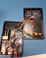
I have just made the Scullcom version using the 1.4 boards. (didn’t notice there were some 1.5’s!.)
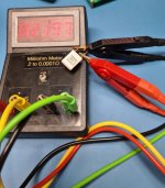
Just finished it and its working fine. I ordered the 1.4 boards by mistake but implemented the 1.5 changes.
Getting hold of the 2V voltmeter (YB5145B) was difficult to find in the UK. I could only get 200mV version. After a lot of mucking about I found a way to convert the 200mV to a 2V version.
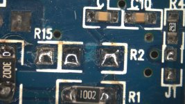
1) Remove 2 resistors, RA and R1,
2) Put a 100k at R1 and a 11K at R2.
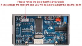
3) Then change the decimal point link to 2V.
(It should be 10K at R2 but I couldn’t get the bourn pot to set it to 1.999 Volts.)
China seems to have a lot of 200V versions, suspect they could be modified the same way.
I have 2 boards and 2 modified Voltmeters if anyone in the UK wants to have ago.
(I also changed the 5V voltage regulator (MIC39100-5.0WS) because the one specified seems to be either discontinued or a very long wait, C10 becomes a 1microF Tant and C5 a 220microF electrolytic with a > 100mOhm ESR for stability reasons for this chip)
Milliohm Meter Version 1.5 - Barbouri's Electronics Projects
scully incorporated it into an update:
Milliohm Meter Update – Scullcom
I have just made the Scullcom version using the 1.4 boards. (didn’t notice there were some 1.5’s!.)
Just finished it and its working fine. I ordered the 1.4 boards by mistake but implemented the 1.5 changes.
Getting hold of the 2V voltmeter (YB5145B) was difficult to find in the UK. I could only get 200mV version. After a lot of mucking about I found a way to convert the 200mV to a 2V version.
1) Remove 2 resistors, RA and R1,
2) Put a 100k at R1 and a 11K at R2.
3) Then change the decimal point link to 2V.
(It should be 10K at R2 but I couldn’t get the bourn pot to set it to 1.999 Volts.)
China seems to have a lot of 200V versions, suspect they could be modified the same way.
I have 2 boards and 2 modified Voltmeters if anyone in the UK wants to have ago.
(I also changed the 5V voltage regulator (MIC39100-5.0WS) because the one specified seems to be either discontinued or a very long wait, C10 becomes a 1microF Tant and C5 a 220microF electrolytic with a > 100mOhm ESR for stability reasons for this chip)
Attachments
Last edited:
....... It should be 10K at R2......... ......
It should be 11.111,11..k
10:1 divider with 100k on top. N-1 is 9. 100k divided by 9 is 11,111.1111111Ω.
Yes, these are all 199mV meters so the "200V" model is only different with a 1000:1 divider. 1Meg and 1k could be good. (1Meg and 1001.001,001.. or 999,000 and 1000 would be gooder but.)
Last edited:
Thank you, that explains a lot 🙂, the photo I had of the 2V one had R2 at 1002, suspect tolerance of this resistor allowed the pot to bring the meter into spec..... but who knows....
Barbouri implemented a nice PCB and design of Scullcomm's Milliohm meter.
Just finished it and its working fine. I ordered the 1.4 boards by mistake but implemented the 1.5 changes.Milliohm Meter Version 1.5 - Barbouri's Electronics Projects
milliohm-meter-update/"]Milliohm Meter Update – Scullcom
.....
LOVED that project, very well designed and made 🙂