I have a pair of 300B monoblocks (currently running EML meshplate 300B 2.5V filaments). They have lovely midrange and plenty of bass in my system. I am consistently thinking the hum is a bit much and the top-end is a little rolled off. With 2.5V filaments, I get 5mV hum and with 5V filaments, I get about 6-7mV hum. This is with AC filaments and humpots.
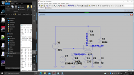
The build currently uses a 6C6 into 300B as shown in schematic.
I am thinking of rebuilding these with the goal of reducing hum as well as increasing top-end extension a bit. Currently, they roll-off at about 10KHz.
I am thinking a larger chassis may facilitate changes so additional stages could be incorporated if needed.
Goals:
1) Reduce hum
2) Improve HF extension
3) Keep with early tube "flavor" but not at the expense of sonics.
4) Would like to keep the 6C6 driver as I have a LOT of nice examples of these.
5 Move to a 5V filament 300B as meshplate 300B 2.5V tubes are becoming very hard to source.
Any suggestions would be welcome.
Schematic below with changes to accommodate the 300B tube.

I would guess you need a buffer in between (mosfet or cathode follower) to drive the grid miller cap of the 2A3, and a floating DC supply for the 2A3 heater.
If you move to a 5v 300b, then consider DC heating. Many of us use Rod Coleman filament regs and they work a treat. Rod is hugely experienced in designing these kind of DC regs. See Lyrima website - copious support too. I use a 9+9v 50VA transformer to supply the regs but you have choices here.
With DC supply also consider 6B4G or Russian 6C4C, both of which can sound very good. More the 2a3 type sound. The grid leak for all these is 500K in the data sheets, which is easier on the input tube. I see you have 270K, which would be the case with a 300b.
I would change the cathode bypass caps to DC Link caps. Kemet C4AQ or Vishay for instance. That should give you more detail and definition. They're rectangular and quite compact.
You may not have to use larger chassis, just improve what's there. For the DC filament supply, you can build that in an outboard case and feed it in using 4 pole XLR connectors. That way you don't take up room in your existing chassis. If you want overkill, use a choke input filament supply or one with a small first cap. It's a nice touch and a small but audible upgrade.
Audio friends have been recommending and using SMPS supplies, which I know nothing about, but maybe someone could come in with a design for those for a 300b or indeed the input tube filaments too. They recommend Meanwell.
That is along the lines I was thinking. How to do a follower is my next question. Can I use another 6C6? Any benefit from using DC on the 6CC filaments?
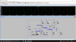
I guess you could in triode mode. Plate & g2 to supply, grid to 91k, cathode through resistor to ground, ac couple cathode to 2A3 as before. Should help a lot at HF.
I guess you could in triode mode. Plate & g2 to supply, grid to 91k, cathode through resistor to ground, ac couple cathode to 2A3 as before. Should help a lot at HF.
I dug up the 6C6 in triode mode, and the data sheet recommends tying G2 and G3 to the plate. It's only a mu of 20 in triode, though, so no more useful than a 6J5 which is a true triode. I'm guessing you need a mu of 30-40.
For the sake of transparency, adding a third stage would compromise what you can achieve with 2 stages. Plus you'd need bigger chassis when you're probably OK with the chassis you presently have. Plenty of 2 stage designs work well. And plenty of circuits always being discussed here.
So changing the cathode bypass caps is easy. Will that help my HF extension?
if I want an all out assault on controlling my hum issue, would you DC heat the 6C6s as well as the 300Bs?
if I want an all out assault on controlling my hum issue, would you DC heat the 6C6s as well as the 300Bs?
So changing the cathode bypass caps is easy. Will that help my HF extension?
if I want an all out assault on controlling my hum issue, would you DC heat the 6C6s as well as the 300Bs?
Probably wouldn't affect the HF extension but you'd most likely get better sound - I upgraded all my cathode bypasses to DC Link, audibly better.
Don't know about DC on the 6C6. I guess just try it but do the outputs first.
I was just discussing Mean Well SMPS units and they do a 5v/3A which I'm going to try on my 300b filaments - cheap enough experiment. I assume the output is isolated? Never used these devices - maybe somebody can comment?
Usually they are isolated. Recommend you add 100nF ceramic on each output to ground as they can generate quite a bit of common mode switching noise.
One option on the first stage is to increase the current and reduce the plate resistor. This will reduce the miller effect and improve the HF. The gain will drop but that's OK with modern high level inputs. The supply dropper resistor will need adjusting to bring the HT on the first stage back to 295V.


So here's the version with 6C6 cathode follower - not ideal could do with something with a bit more guts (Mu) as Andy pointed out.

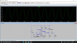
Here's the mosfet version - this device has relatively low gate charge. You could 'hide' this under the chassis only you would know, and is easy to retrofit.

You may want to add a small resistor in series with the .22uF in case you drive the 2A3 grid into conduction.
Just some ideas.

Here's the mosfet version - this device has relatively low gate charge. You could 'hide' this under the chassis only you would know, and is easy to retrofit.

You may want to add a small resistor in series with the .22uF in case you drive the 2A3 grid into conduction.
Just some ideas.
Last edited:
I was just discussing Mean Well SMPS units and they do a 5v/3A which I'm going to try on my 300b filaments - cheap enough experiment. I assume the output is isolated? Never used these devices - maybe somebody can comment?
Not all of them are isolated - if it comes with a 3-pin mains/line connector, measure between PE and the output 0V. Some use the PE as an EMC ground. Grounding the 0V output is like short-circuiting your cathode resistor, or FIL- terminal, in a DHT amp!
You can try to use them directly on the filament, but remember that (with a DHT) the heating current flows in the same wire as the anode current. This means a direct mixing of the music signal with all the broadband noise.
Also, the SMPS output is voltage-regulated, so the PSU will respond to the differential music-signal (across the filament) by trying to cancel it out.
But I know that you always listen to your modifications, so you will soon hear how bad that will sound.
You can also try using them as a Raw DC supply to feed a purpose-designed filament regulator (ahem, like mine for example). This will certainly function, so long as you check that its 0V output is not connected to PE.
The downside here is the large amount of common mode noise-current, mentioned already above. This is mostly generated by the switching action, and appears in large amounts at switching frequency and harmonics, and from 100-400MHz due to switching edges. The amplitudes and frequencies may vary with load, so don't test it open-circuit! The noise is of such high frequency that it easily passes through the capacitance of the unit's transformer, and can reach into the mA range - check the datasheet for "Leakage Current".
This is common-mode noise, so can only be filtered with common-mode chokes, and pairs of caps to ground. Trouble with the caps is that they are now in parallel with your cathode bypass capacitor.
The DHT circuit usually does not care about the noise above 20kHz, but allowing this noise-current to circulate in your audio system ground can degrade the performance of your DAC, depending on whether the DAC is routed to PE somehow (eg via a computer, DVD drive, CD player). Ground-noise can also degrade any preamp stages with op-amps designed before about 1998. (Later op-amps are designed to counter rectification-effects from broadband noise).
Try them for the experiment, but be sure to compare by listening with known-good solutions.
Rod Coleman is always much too modest about current sourcing the filaments of audio valves. We need to always bear in mind that any garbage that appears from averaged filament voltage to signal ground is exactly as important as voltage from grid to signal ground. And, that signal current through the valve is distributed between our intended path (nice wirewound resistor and boutique flavour of the week capacitor) and a significant stray path (largely undefined heating power supply leakage elements).
Minimizing the stray path isn't trivial, and it isn't pretty or low-loss, but it's needed if you really, really must play with valves without separate cathodes. Might be worth it, if you really want those curves. Real triodes have curves.
All good fortune,
Chris
Minimizing the stray path isn't trivial, and it isn't pretty or low-loss, but it's needed if you really, really must play with valves without separate cathodes. Might be worth it, if you really want those curves. Real triodes have curves.
All good fortune,
Chris
Still if you have one handy its worth a go. I could suggest splitting the cathode resistor and cap into two (twice R and half C) and connecting each branch to one side of the cathode/heater. Add two ceramics to ground and the floating supply across. Use a supply at 2 x heater current rating as it may not start when cold.
I was wondering if you could go the other way and run the heater off 200KHz say with a balanced transformer and some mosfet multi-vibrator on the other side.
I was wondering if you could go the other way and run the heater off 200KHz say with a balanced transformer and some mosfet multi-vibrator on the other side.
Last edited:
The 135 volt on the 6c6 plates limits the max voltage sving a lot. If you consider keeping the 6c6. You probably will get better performance with a ccs or an IT. Given the high ra of the 6c6 it might be challenging to get IT's with enough henry. 🙂
Regarding heating the input tube with a SMPS, discussions with one who has tried this suggest that for the Mean Well ones you bolt the metal case to the chassis and connect the 0v DC directly to the safety earth/chassis and not the signal ground. These are 5v and 12v which would need a dropper resistor. A cap after the resistor should be no more than 470uF I'm told, to avoid hiccuping.
Already planning on the Coleman Regs as I've already purchased a set for the 300Bs. Wondering if I should get a second set for the 6C6?
I am not sure what IT stands for.
The CCS sounds interesting as well as the cathode follower but I need some clarification as I'm pretty new at all this.
Changing a few passive components as baudouin0 suggested is attractive! I do have enough gain although almost all of my listening is based on vinyl with appropriate phono-stages.
- Home
- Amplifiers
- Tubes / Valves
- 300B Amp Improvement Suggestions Needed