Hi. I was playing with a triode and i noticed that the lowest harmonic distortion point is different depending on the signal amplitude. At 1vpp grid signal, i need to have a different bias current than at 3vpp.
Edit. If i then setup the bias to have lowest distortion for a signal at 3v, i then have more at 1v.
Is center biasing variable, or should i not use harmonic distortion as a center bias indication ?
Thank you
Edit. If i then setup the bias to have lowest distortion for a signal at 3v, i then have more at 1v.
Is center biasing variable, or should i not use harmonic distortion as a center bias indication ?
Thank you
Last edited:
The operating point is a rough point for a design. In reality B+, power supply droop, Ra, Rk, inductance/capacitance and the resulting tube construction itself plus others such as variation vs temperature etc in addition to the intended effect.
If your goal is to take a input Vpp of 10V and output as low distortion as possible then it will have design parameters different to one that is intentionally designed to add harmonics or cancel harmonics.
Just from my limited experience it is a large area - not only from a single tube perspective but also in multi-stage and architecture effects.
You get different amounts of harmonics depending on the input - yes. On a standard class A amp, as you turn up the volume the amp is still running the same set current and voltage. Only difference is that the voltage swing input is getting bigger, resulting in more distortion (depending on parameters).
The reason I say capacitance and inductive loads at the start is that makes the load line not a straight line but an ellipse. So the simple answer is yes but there's a more complex answer too.
Lowest distortion does not indicate centre bias, unless your test signal is close to clipping. For a single triode, the small-signal distortion gets lower at smaller bias voltages. It sounds like your 3Vpp signal is close to clipping (I'm guessing you using a 12AX7?)Hi. I was playing with a triode and i noticed that the lowest harmonic distortion point is different depending on the signal amplitude. At 1vpp grid signal, i need to have a different bias current than at 3vpp.
If you have more than one valve stage in cascade then it is more complicated because of distorton cancellation effects.
Thank you very much. Can i simulate this in ltspice ? it is a single triode 12ax7 gainstage.
Why do i center bias if it does not get me lowest distortion. I seems slightly colder bias have lower distortion ?
How can i center bias accurately because i can use math formulas but i tried it on real tubes ? Because if i want lower imd, do i have to center bias ? Or bias for the lowest harmonic distortion ?
You will need to model the load line - perhaps one of the load line calculators such as:
Triode / Pentode Loadline Simulator v.1.0 (20161216 [url]www.trioda.com)[/url]
The above shows distortion as part of the calculation - although the caveat is that it's a line rather than anything more complex.
Universal loadline calculator for vacuum tubes - Vacuum Tube Amplifiers - DIY
And to a lesser extent:
Interactive Valve Data Sheets
Yes - you can simulate a 12ax7 in ltspice. However note that the model is near to the tested tube, your tube may vary a little in reality.
Use the typical curve table of that tube and fix a load line.
And leave the simulation; take a socket, three resistors, two capS and a HT voltage power with the possibility to change the voltage.
Then with a good sound card and ARTA sw you can see what happen.
In addition if you change the brand for the same type of tube it easy to see some changes
And, of course, the THD varies with level of the input signal.
Each
Using a triode, the harmonic distortion should be proportional with signal level. I.e., distortion goes up as signal levels go up, while distortion should decrease as signal levels are decreased.
Testing a simple common cathode stage in LTspice is a great way to get a feel for how different operating conditions yield differing results.
Note that with a 12AX7, distortion will vary a lot depending on the value of Rload (the input resistance of the driven stage after your 12AX7 'preamp'). 12AX7 has a high rp (internal plate resistance) which means it can't drive a load resistance of lower than about 150k ohms without significant losses. You'll want the load resistance to be at least 2X the rp of the 12AX7 (which is about 60k to 80k ohms, depending on operating point chosen).
Here's a test circuit for LTspice. You may have to change the 12AX7 model to something you have in your setup.
Rload (simulates load resistance of driven stage) is set to 100k, so THD is quite high. Increase Rload to 220k, 470k or 1M ohms and see the output level increase and THD decrease. You'll see that 12AX7 is really 'touchy.' It can be loaded down very easily.||
Of course, now the question is 'why?'.
Attachments
Last edited:
Why do i center bias if it does not get me lowest distortion. I seems slightly colder bias have lower distortion ?
You would center bias the tube to be able to apply the largest clean signal to the grid and have the highest power out. Maximum volume for power without (+) clipping or sending the tube into cutoff (-) side, too soon. But if max power isn't critical then you can move the biasing away from center if you want it that way for any other reason.
Thank you very much all. I will recap :
- Center biasing is not mainly for lower THD, it is to accommodate the biggest signal in without cutoff (grid at 0v ?) and allow the biggest output swing without clipping. thanks 20to20.
- Setting the bias for lowest THD (1khz sine) does not warranty a center biased tube. thank you Merlin. you also said : "unless your test signal is close to clipping" so should i get the tube a very high signal make it clip, then adjust for the lowest thd output, to find center bias without plotting the loadlines ?
- thd is dependent on the output load or input impedance of the next stage, and on the plate load (any cons in using a High plate load to lower THD ?)
rongon, thank you for the file but i cant run it, it tells me it misses the tungsol model. Its very kind of you, i use ltspice as a schematic editor, i run very low simulations as i never get enough experience to trust it.
As for your question to why, am I right if I say it is because it is a low current tube ?
Waltube, yes when i use a bigger sine wave the thd increase with both bias. I will invest in a good usb soundcard a focusrite maybe, thank you.
EDIT : off topic but, why i have so many blank lines in my posts between lines ?
Last edited:
Using a triode, the harmonic distortion should be proportional with signal level. I.e., distortion goes up as signal levels go up, while distortion should decrease as signal levels are decreased.
Testing a simple common cathode stage in LTspice is a great way to get a feel for how different operating conditions yield differing results.
Note that with a 12AX7, distortion will vary a lot depending on the value of Rload (the input resistance of the driven stage after your 12AX7 'preamp'). 12AX7 has a high rp (internal plate resistance) which means it can't drive a load resistance of lower than about 150k ohms without significant losses. You'll want the load resistance to be at least 2X the rp of the 12AX7 (which is about 60k to 80k ohms, depending on operating point chosen).
Here's a test circuit for LTspice. You may have to change the 12AX7 model to something you have in your setup.
Rload (simulates load resistance of driven stage) is set to 100k, so THD is quite high. Increase Rload to 220k, 470k or 1M ohms and see the output level increase and THD decrease. You'll see that 12AX7 is really 'touchy.' It can be loaded down very easily.||
Of course, now the question is 'why?'.
"Couldn't find symbol(s):
12AX7_TungSol_i4 "
Thank you very much. Can i simulate this in ltspice ? it is a single triode 12ax7 gainstage.
Why do i center bias if it does not get me lowest distortion. I seems slightly colder bias have lower distortion ?
How can i center bias accurately because i can use math formulas but i tried it on real tubes ? Because if i want lower imd, do i have to center bias ? Or bias for the lowest harmonic distortion ?
If looking for a real-tube method...
With a curve tracer like eTracer or uTracer, you can run out the curves for any tube, then immediately drag and drop any operating point you want and get a direct calculation of distortion nodes 2, 3, 4, 5... using the load line tool against the actual curves you just created with a real tube. No dependency of a model, you're using the actual tube just analyzed. And by varying any parameter, plate load, plate voltage, mA, grid bias, swing, etc. to "explore" many operating points in a few minutes. This is a real-tube solution that uses math, everything else is a modeled tube.
A search for 12ax7 in the LTSpice thread may reveal some current models.
I've found the Ayumi models to be quite good. Here is his 12AX7 model.
Code:
*
* Generic triode model: 12AX7
* Copyright 2003--2008 by Ayumi Nakabayashi, All rights reserved.
* Version 3.10, Generated on Sat Mar  8 22:41:09 2008
*             Plate
*             | Grid
*             | | Cathode
*             | | |
.SUBCKT 12AX7 A G K
BGG   GG   0 V=V(G,K)+0.59836683
BM1   M1   0 V=(0.0017172334*(URAMP(V(A,K))+1e-10))**-0.2685074
BM2   M2   0 V=(0.84817287*(URAMP(V(GG)+URAMP(V(A,K))/88.413802)+1e-10))**1.7685074
BP    P    0 V=0.001130216*(URAMP(V(GG)+URAMP(V(A,K))/104.24031)+1e-10)**1.5
BIK   IK   0 V=U(V(GG))*V(P)+(1-U(V(GG)))*0.00071211506*V(M1)*V(M2)
BIG   IG   0 V=0.000565108*URAMP(V(G,K))**1.5*(URAMP(V(G,K))/(URAMP(V(A,K))+URAMP(V(G,K)))*1.2+0.4)
BIAK  A    K I=URAMP(V(IK,IG)-URAMP(V(IK,IG)-(0.00058141055*URAMP(V(A,K))**1.5)))+1e-10*V(A,K)
BIGK  G    K I=V(IG)
* CAPS
CGA   G    A 1.7p
CGK   G    K 1.6p
CAK   A    K 0.5p
.ENDSThank you Ray Waters, and also Thank you Rongon (your file is amazing it also tells the voltage without hovering on the nodes, its amazing).
Here is the simulations, things happens.
1vpp signal = the hotter the bias the less distortion i have.
3vpp signal = same thing the hotter the bias the less distortion i have... wierd
5vpp signal = same thing
So at this point i looked through my real life circuit and remembered I did not use a cathode capacitor, so I restarted the sim without this cap and, now I can see that the cathode resistor has an effect on thd. And now there is a center point where the hotter I go the higher the distortion.
Can someone confirm this ?
Last edited:
Hi again. It seems the sim is accurate and confirm what I experience in real life. The colder the less thd, but you are right it is way off and not center biased. this the result i found when I dont use a cathode capacitor.
For a 10vpp input (i pushed it hard to see the clipping) here are the results for each cathode resistor, this is from the rongon sim, 122k plate resistor :
100r=1.7mA (+179.1 -89.5) thd=25.6%
698r=1.28mA (+138.9 -138.9) thd=14.9%
713r=1.27mA (+138.1 -139.8) thd=14.7%
6K= 0.43.mA (+16.2 -67.8) thd=10.2%
EDITED too much numbers and decimals...
The number in parenthesis are the transient voltage out with a 1meg load.
Last edited:
I've found the Ayumi models to be quite good. Here is his 12AX7 model.
*thumbs up* - sorry I didn't have a time to make a search in the thread 🙂
Thank you Ray Waters, and also Thank you Rongon (your file is amazing it also tells the voltage without hovering on the nodes, its amazing).
Here is the simulations, things happens.
1vpp signal = the hotter the bias the less distortion i have.
3vpp signal = same thing the hotter the bias the less distortion i have... wierd
5vpp signal = same thing
So at this point i looked through my real life circuit and remembered I did not use a cathode capacitor, so I restarted the sim without this cap and, now I can see that the cathode resistor has an effect on thd. And now there is a center point where the hotter I go the higher the distortion.
Can someone confirm this ?
Normally the more B+ the lower the distortion, also the lower the current swing (ie flatter load line) the lower the distortion. Lastly feeding back through a cathode cap causes high amplification at the cost of increasing distortion (not sure if this is simply due to the larger input signal or the fact that the positive feedback is shifted in phase), or additional harmonics input.
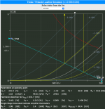
If you look at the parameters in these photos, under harmonic distortion:
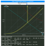
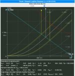
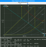
The increasing size of the input wave form incurs a larger distortion.
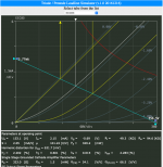
Now have a look at the same rough size input and moving the operating B+ voltage - however the web page is flawed in that you can't move the OP closer to the dissipation line thus you end up in the non-linear area and hence more distortion compared to real life:
Some misconceptions here. A cathode bypass capacitor eliminates NFB and thereby increases gain. There is no positive feedback.
If the bypass caps not used you get minor gain a little bit less on THD but an higher Zout of the stage
So you must take a better care on Zin of the load.
Is not a grat idea with 12AX7A specially
Walter
So you must take a better care on Zin of the load.
Is not a grat idea with 12AX7A specially
Walter
- Home
- Amplifiers
- Tubes / Valves
- If i have the lowest harmonic distortion does it mean my triode is center biased