The fet will pull up the voltage as a low impedance source but to relax the voltage the 33k is the pull down source.Are you sure?
Let us think about it with a sine wave;
The positive going edge will work into say a 5k load easily but the negative edges will not. The negative edges will work into 47k nicely because the 33k is pulling it down as the fet relaxes and see little obstruction. Into a lower impedance the negative edge will have a hard time keeping up and will distort the waveform.
Pretty obvious really.
My intended use here is to add 9dB of gain to a phono preamp, to bring that up to the same subjective level as my DAC's output. This line stage would go between the output of the phono preamp and the input of my 'passive preamp' (input switch and Intact Audio autoformer volume control).
You could also do what I did, namely turn the passive pre into an active by using the autoformer as an "output transformer" in parafeed, as well as a volume control. Stacked 3x3 in the core this works very well. My 26/01A preamp/DAC does this and it sounds fantastic. I'm using the Bent Audio TAP-X which is the remote controlled version of the Intact autoformer.
Here's a shot "under the hood" of the preamp/DAC. Power supply is in a separate box.
Attachments

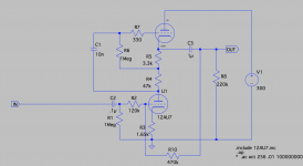
I did something similar, but with a mu-follower. Originally no feedback, not so great sounding, but sounds pretty good with feedback. Probably would be better with more current through the tube, but it was meant to fit into a PAS preamp with its wimpy power transformer. I think this is the version I built, there were 2 on my drive. I also simulated a 6SN7 version with no current limitation, that would probably be better.
Morgan Jones dismisses the one and two stage tube feedback circuits* due to considerations for noise and for loading of the volume control (which I don't fully understand).
*pages 499-500 Valve Amplifiers, 3rd. ed.
Morgan Jones dismisses the one and two stage tube feedback circuits* due to considerations for noise and for loading of the volume control (which I don't fully understand).
*pages 499-500 Valve Amplifiers, 3rd. ed.
Attachments
The fet will pull up the voltage as a low impedance source but to relax the voltage the 33k is the pull down source.
Let us think about it with a sine wave;
The positive going edge will work into say a 5k load easily but the negative edges will not. The negative edges will work into 47k nicely because the 33k is pulling it down as the fet relaxes and see little obstruction. Into a lower impedance the negative edge will have a hard time keeping up and will distort the waveform.
Pretty obvious really.
Yes, you are correct.
However, this is different from saying the output impedance is 33k ohms. With this particular circuit, in simulation, 1V rms can be swung across 250 ohms before the negative going half of the output waveform clips. I called the output impedance 250 ohms because that was where the negative half clips with 1V rms out.
Had I reduced the output voltage to 100mV rms, I could have claimed a lower output impedance.
If I raise the output voltage to 2V rms (digital 0dBFS), then the output impedance would have to be raised to (my guess is) 500 ohms.
At any rate, into a more normal load like 10k ohms, this circuit can swing far more than just a couple of volts. With a 47k ohm load and 1V rms 1kHz signal input, the output is 2.9V rms still at lower than 0.01% THD.
I think a spec like "Zout = xxx" needs to have a qualifier attached - Into what load and at what level(s)?
You could also do what I did, namely turn the passive pre into an active by using the autoformer as an "output transformer" in parafeed, as well as a volume control. Stacked 3x3 in the core this works very well. My 26/01A preamp/DAC does this and it sounds fantastic. I'm using the Bent Audio TAP-X which is the remote controlled version of the Intact autoformer.
Cool beans, indeed!
What's the insertion loss of the autoformer?
Cool beans, indeed!
What's the insertion loss of the autoformer?
I didn't measure insertion loss per se, however I'm using a LL1676 input transformer 4:2 to drop the 2Vrms input to 1V, then the DHT (26 or 01A) applies a mu of 8, and the autoformer is used to attenuate (or provide gain to) the resulting signal. I usually listen at -15 to -9db on the autoformer attenuator but the autoformer can provide up to +7db gain as well. Very handy to have the flexibility as some recordings are much lower in level than others.
I initially used an OPT before the autoformer but found it was unnecessary and indeed the sound was much better without it. I use damped-resonance parafeed with the autoformer as the OPT to tailor the low freq rolloff, which is 4.8Hz -3db without the usual parafeed peaking.
The thing is, if you put the gain stage right in front of the volume control, that gain stage will always have the full output from the sources into its grid (input), which guarantees that it will be running at higher signal levels all the time, with the higher distortion that comes with it.
Let's say the gain stage has 3X (9.5dB) gain.
Let's use a DAC as our signal source, with the usual output of 0dBFS = 2V rms.
If the volume control is right after the DAC output and is set to -20dB (10X) attenuation, then the amplifier that follows sees 0.2V rms at its input, amplifies that to 0.6V rms out.
If the gain stage comes before the volume control, right after the signal sources, then the gain stage sees all 2V rms at its input. If the amplifier amplifies that by 3X, then there is 6V rms sent to the volume control input. Attenuating that by 20dB (10X) brings it down to 0.6V rms. But the gain stage is still running with 2V rms in and 6V rms out.
Is that desirable?
The thing is, if you put the gain stage right in front of the volume control, that gain stage will always have the full output from the sources into its grid (input), which guarantees that it will be running at higher signal levels all the time, with the higher distortion that comes with it.
Let's say the gain stage has 3X (9.5dB) gain.
Let's use a DAC as our signal source, with the usual output of 0dBFS = 2V rms.
If the volume control is right after the DAC output and is set to -20dB (10X) attenuation, then the amplifier that follows sees 0.2V rms at its input, amplifies that to 0.6V rms out.
If the gain stage comes before the volume control, right after the signal sources, then the gain stage sees all 2V rms at its input. If the amplifier amplifies that by 3X, then there is 6V rms sent to the volume control input. Attenuating that by 20dB (10X) brings it down to 0.6V rms. But the gain stage is still running with 2V rms in and 6V rms out.
Is that desirable?
I've seen no issues. I do cut the signal in half with the LL1676 before the gain stage; that also allows me to use battery grid bias with a 9V lithium on the secondary of the LL1676 with no DC-blocking cap needed. Talking to Dave Slagle when I put this together years ago he was confident a 3x3 stack of the autoformer core could easily handle that signal level, and would have about 150H inductance. I'm very happy with the results.
- Home
- Amplifiers
- Tubes / Valves
- Recurring Question: Low Gain Tube Preamp?