Hi all
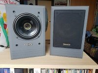
My dad (who is now a retired carpenter and bored), recently purchased a set of working System 6 NFM II's, which aside from some slightly tatty cabinets, also happened to come with a cardboard box containing two brand new dual concentric drivers.
I've managed to find a copy of the original "Operating and Service Manual" for the NFM and DMT series which has the spec and even the available replacement items from the day listed. While it gives the cabinet dimensions and crossover components (even complete crossover unit part numbers), there is no schematic.
The plan is to build a new set of 'modern' cabinets keeping the dimensions roughly the same and the internal volume, and provide new terminals, crossover and port with the drivers in the box, making another set, updating the components to a better quality in the process.
Does anyone have, or know of, the correct schematic for the crossover? I have searched and searched t'internet for it, and while I can find plenty on the System 600 and MG15, I can't seem to find anything on the 6 NFM II. The existing crossovers are covered in a resin / glue substance (presumably to stop vibrations), making component identity and routing pretty tricky, and I don't want to damage them by trying to remove it - especially as they are in use at the moment, and sounding great 😀
Any advivce or info would be gratefully appreciated.
I can add the info that the crossover is 2nd order LF, 1st order HF with positive acoustic polarity.
Crossover frequency is 2,000 Hz and nominal impedance is 8 Ω.
NFM stands for Near Field Monitor for pro use, so there may be no baffle step correction in the crossover.
Crossover frequency is 2,000 Hz and nominal impedance is 8 Ω.
NFM stands for Near Field Monitor for pro use, so there may be no baffle step correction in the crossover.
If you can supply the list of crossover components, assuming their values are given, someone may be able to deduce the crossover schematic for you, in light of the earlier information I supplied.While it gives the cabinet dimensions and crossover components (even complete crossover unit part numbers), there is no schematic.
Last edited: