Οκ tell us more
what is the bias of this circuit and what determine the bias
i dlike to know more as a picture remindes the operation og QSC but never seen that before done with mosfets
i like symmetric circuits but i am not shure about that ( or was it akg ? )
what is the bias of this circuit and what determine the bias
i dlike to know more as a picture remindes the operation og QSC but never seen that before done with mosfets
i like symmetric circuits but i am not shure about that ( or was it akg ? )
what is the bias of this circuit and what determine the bias
Ok, well, it's chain dependent.
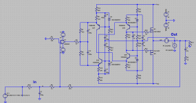
Four zeners D1,D2,D3,D4 and four emitter resistances R9,R10,R11,R12 defines current through Q17,Q18,Q19,Q20.
In couple with R1,R5 current the whole chain creates strictly dependent current through R33 which can be easily swapped with a simple LED (red, no high-voltage-drop ones).
The whole chain are excited by opamp's output current.
i dlike to know more
This curcuit are worth to try.
Ask what you want to know about.
Your circuit reminds me of LES_7777 from vegalab
Yes.
Very clever topology, though, I would use 3503/1381 Fairchild transistors instead of Hitachis, the latter are almost impossible to obtain.
In the OPS gates even 3904/3906 or bc550/560 based on accessibility in EU and preferred bias current.
5 mA are well enough, but there are no limit in the sky.
😉
In first stage Hitachis are well known performers and now produced elsewhere from Rochester and up to ISC and unnamed chineese. 3503/1381 could become bottleneck, i'ld prefer something with higher Ic.
TTC011/TTA006, KSA1220/KSC2690, 2SC3421/2SA1358, 2SC4793/2SA1837, 2SC5171/2SA1930.
as anyone built this amp?
Of course. There are even at least three differently routed boards. But unfortunately all of them for TO-3P cased k1058/j162
One idea will be to use a P101 circuit that will be easy
I wonder though is it possible to operate a p101 in high bias
I wonder though is it possible to operate a p101 in high bias
One idea will be to use a P101 circuit that will .be easy
Aaargh...
Just check how perfect an attached pcb.
I wonder though is it possible to operate a p101 in high bias
Again, they don't need high bias.
You're trying to use scalpel to crack bones.

If we want to fight the influence of parasitic capacitances, BesPavs circuit seems better. However P101 has less silicon junctions.
P101 has less silicon junctions.
It seems you really want to try the P101 anyway….
P101 are ugly even by topology.
First - dominant pole compensation, C3 at the original schematic. Putting itbetween two high-impedance points in the actual device you just drop out at least 40 dB of feedback depth at high audio frequencies resulting in poor transistor-named sounding and proportional THD rise.
Second - straight VAS loading to OPS gates adds its part to slowdown brilliant latfets in such a cheme.
Third - due to low transconductance such a latfets need up to +10 V at gate-source junction. P101 are very bad in OPS devices SOA perspective. It meant you add second pair for keeping inside SOA, but even increasing OPS input capacitance and double fallback in speed.
So, no, p101 did not deserve a try.
Bespav
You may have misinterpreted my sarcastic statement…because I do not recommend the P101 for an hi-end system.
I remember that it has a very slow slew rate too.
Fab
You may have misinterpreted my sarcastic statement…because I do not recommend the P101 for an hi-end system.
I remember that it has a very slow slew rate too.
Fab
Last edited:
You may have misinterpreted my sarcastic statement…
No-no, your sarcastis tone was just needed a little technical argues. So i provided them.
over the years, i've seen people comment about about speed of amps with lateral mosfet ops. if you have that concern, it might be worthwhile to look at some spectral designs - they are high speed designs that (i think) used lateral mosfets in their ops.
ok, my memory was not quite as bad as i thought. here's an internal shot of a dma-50 power amp:
Spectral Audio DMA-50 Megahertz Stereo Amplifier – SkyFi Audio
ok, my memory was not quite as bad as i thought. here's an internal shot of a dma-50 power amp:
Spectral Audio DMA-50 Megahertz Stereo Amplifier – SkyFi Audio
Last edited:
look at some spectral designs
Are there a way to look at schematic?
I presume so, but I don't have any.
However, the designer, Demian Martin, is a member here and might have some useful info.
However, the designer, Demian Martin, is a member here and might have some useful info.
Based on informations can be gathered from the web, it seems that it’s all about the speed here. Complementer symmetric topology, cascoded jfet input, cascoded bjt VAS and VFET (not lateral) output.
J50-K135
Please check this out !
2SK1058 and 2SJ162 amplifiers Collection
Got me plenty of those and actually dont know what to do with them
My gut says that no mater how i operate them , they will never beat the 1302-3281 combo .
so ok got a secondary set of 2way speakers that i would like to operate in reality those are sensitive 30W real power speakers so power of the amp is not the issue .... one pair of those will happily produce 60 W ...
so the idea is to go for something diferent How about a tube mosfet combo and highly biased ?
has anyone seen a schematic like that that operates with these transistors ?
if so please let me know
Other suggestions are also welcome but still i think what ever this should be in high bias
Please check this out !
2SK1058 and 2SJ162 amplifiers Collection
did you look at the internals photo in the link i posted?
...VFET (not lateral) output.
Yes, you're right. LATFTs were used in the vintage models. The newer models are built with VFETs according to Spectral’s website.
"Our breakthrough topology time aligns high-current vertical fet output devices for rapid, pistonic signal launch. The output section is comprised of eight individual V-fet amplifier modules paralleled to achieve a minimum 200 watt RMS / per channel with 60 amp capability. With this “Focused Array” arrangement of parallel fet amplifiers, full rated power is delivered with total load stability at an unprecedented 1 MHz." - DMA-250
"Our breakthrough topology time aligns high-current vertical fet output devices for rapid, pistonic signal launch. The output section is comprised of eight individual V-fet amplifier modules paralleled to achieve a minimum 200 watt RMS / per channel with 60 amp capability. With this “Focused Array” arrangement of parallel fet amplifiers, full rated power is delivered with total load stability at an unprecedented 1 MHz." - DMA-250
Last edited:
I have tried to improve the DH-200 sound but only succeeded marginally thus I quit and concentrated on designs with different parameters objectives.
P101 sound is not my cup of tea….
Goldmund Telos is good but not enough for my taste.
You should try something very different than the standard blameless or such type of designs…
Based on my humble experience with these transistors - I have used lateral mosfet designs since about 20 years - you can get a very good sound with high bias (ex: push-pull class A), CFA topology (like Accuphase) , low overall feedback, no or extremely small degeneration on mosfet, and good drive current. Since you do not need high power a 20-25W rms class A can be a good candidate….
Fab
Hi Fab,
Are you talking about your items? The USSA5.
The VSSA topology has been developed many times on forum. DIY and commercial products. I don't know why member Lazy Cat run away. Is there technical/financial problem?
Walkalone,
- Home
- Amplifiers
- Solid State
- j50 k 135