I sure hope someone will help me sort out how to wire the AC on the SET mono amps I’m building. I have the power transformer mounted on top of the chassis. I also have an IEC power connector on the rear and the on/off switch on the front. I can’t figure out how to wire this without having just the neutral wire running from the switch to the IEC connector and all the way across the chassis. I know all AC wiring should be twisted but by my way of thinking, I end up with a single wire. I hope this makes sense. Any help will be highly appreciated!
Unless you switch both of the AC lines, that will happen. Or locate the switch on the rear panel.
The switch contacts should be in the "hot" line (black AC wire for USA), if only one switch is used.
The switch contacts should be in the "hot" line (black AC wire for USA), if only one switch is used.
Attachments
Last edited:

AC Wiring
I can’t relocate the switch. Can you switch both lines with a single pole switch? I’d think not.
Unless you switch both of the AC lines, that will happen. Or locate the switch on the rear panel.
The switch contacts should be in the "hot" line (black AC wire for USA), if only one switch is used.
I can’t relocate the switch. Can you switch both lines with a single pole switch? I’d think not.
AC Wiring
I thought this is more simple than other things in the circuit. 🙂[/QUOTE
I’m appreciate the diagram but I still don’t see how I can keep twisted wires throughout the circuit.
If you have to run a single wire to the switch, and a single wire from the switch,
Then be sure that no sensitive wire (grid wire, input stage ground wire), or part (coupling cap) runs near to those wires.
Otherwise, you can get either inductive coupling, or capacitive coupling.
There are times when "something has got to give".
That may require a change in your amplifier, depending on what comes near to those switch wires.
It can, but the chassis cutout is different.
Parts Express IEC AC Power Jack Chassis Mount with 10A Fuse Holder
https://www.mouser.com/ProductDetai...nbyPPNdgKthL-xDC82BcT9toVo5gDveIaAmKAEALw_wcB
Parts Express IEC AC Power Jack Chassis Mount with 10A Fuse Holder
https://www.mouser.com/ProductDetai...nbyPPNdgKthL-xDC82BcT9toVo5gDveIaAmKAEALw_wcB
Last edited:
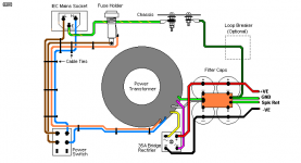
If the switch, power transformer and IEC connector are not on three distant corners of a very large chassis ), the easiest way to imagine it is as a twisted pair from IEC directly to switch via the power transformer location with a break in one conductor, the two ends of which are connected to the power transformer input terminals.
If your fuse holder is separate from the IEC then you just consider it to be in series with the Line (hot) lead from the IEC and twist its output with the other lead (from the 'N' terminal in Rayma's diagram) coming freely from the IEC.
I hope my wording works.
If your fuse holder is separate from the IEC then you just consider it to be in series with the Line (hot) lead from the IEC and twist its output with the other lead (from the 'N' terminal in Rayma's diagram) coming freely from the IEC.
I hope my wording works.
AC Wiring
Yes, the IEC connector has a built-in fuse.
Does IEC come with fuse box?
Yes, the IEC connector has a built-in fuse.
AC Wiring
Good advice, thanks. I have some braided metal sheath. If I end up having to run the single AC wire, should I enclose that wire and ground it to the chassis?
If you have to run a single wire to the switch, and a single wire from the switch,
Then be sure that no sensitive wire (grid wire, input stage ground wire), or part (coupling cap) runs near to those wires.
Otherwise, you can get either inductive coupling, or capacitive coupling.
There are times when "something has got to give".
That may require a change in your amplifier, depending on what comes near to those switch wires.
Good advice, thanks. I have some braided metal sheath. If I end up having to run the single AC wire, should I enclose that wire and ground it to the chassis?
AC Wiring
I’m not sure I understand. Does this mean I can just run a twisted pair from the IEC connector to the single pole switch and then solder a twisted pair from the power transformer to the same locations on the switch? That seems to make sense to me.
If the switch, power transformer and IEC connector are not on three distant corners of a very large chassis ), the easiest way to imagine it is as a twisted pair from IEC directly to switch via the power transformer location with a break in one conductor, the two ends of which are connected to the power transformer input terminals.
If your fuse holder is separate from the IEC then you just consider it to be in series with the Line (hot) lead from the IEC and twist its output with the other lead (from the 'N' terminal in Rayma's diagram) coming freely from the IEC.
I hope my wording works.
I’m not sure I understand. Does this mean I can just run a twisted pair from the IEC connector to the single pole switch and then solder a twisted pair from the power transformer to the same locations on the switch? That seems to make sense to me.
Does this mean I can just run a twisted pair from the IEC connector to the single pole switch and then solder a twisted pair from the power transformer to the same locations on the switch?
No, that wouldn't work. The switch is meant to interrupt or connect a single leg of the AC mains power.
My post was meant as an easy way of imagining it if you want to think mainly in terms of a twisted pair.
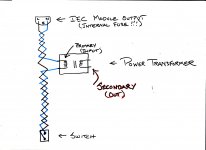
I usually make my layout such that if IEC is on the left rear, and switch is in the left front, I would place the the power transformer somewhere close to a line between the two, twist up enough wire to run from the IEC module output , passing it close to the connections to the power transformer primary and then on to the switch.
Cutting the (blue wire) so as to be able to use the freshly cut ends to connect to the transformer. (Either directly or to a solder tag strip to which the transformer primary is also connected.) There are many ways to do it to be in accord with the rest of your layout.
Note that I left out the safety ground just to keep the sketch simple. The focus is the twisted pair ONLY.
Also the drawing is only for an IEC module with integrated fuse holder. If separate the fuse would appear in series with the Line output of the module.
I hope this is some help.
Attachments
You can run a twisted pair from the IEC+fuse input past the power switch, not cutting the neutral wire, and on to the transformer primary.
All good fortune,
Chris
All good fortune,
Chris
....I hope this is some help.
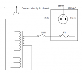
Nice drawing but... aren't both switch wires HOT? So even twisted, the electrostatic field won't cancel?
I think what is wanted is more like this (right side).
Attachments
It should be added that this (to interrupt only "hot" wire) does not work in EU standard system, where the "Schuko" plug can be inserted even upside down.
There must be use double circuit breaker switch.
There must be use double circuit breaker switch.
AC Wiring
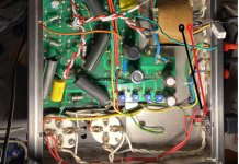
Thanks to everyone who provided input. I sat down and wired the amp last night. It ended up like PRR’s drawing that he provided. I connected the hot wire to the switch. It works as it should and tests okay and almost all the wiring is a twisted pair. Thanks again, everyone!
Nice drawing but... aren't both switch wires HOT? So even twisted, the electrostatic field won't cancel?
I think what is wanted is more like this (right side).
Thanks to everyone who provided input. I sat down and wired the amp last night. It ended up like PRR’s drawing that he provided. I connected the hot wire to the switch. It works as it should and tests okay and almost all the wiring is a twisted pair. Thanks again, everyone!
- Home
- Amplifiers
- Tubes / Valves
- Tube Amp AC Wiring