Hi All,
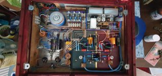
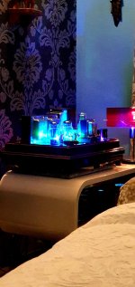
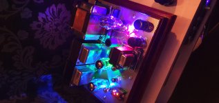
Having finished the Kegger/Blue Glow KT88SE amplifier at the weekend, I tested it and promptly installed for a listen.
I was amazed how good this amplifier sounded and had it on for around 5hrs or so.
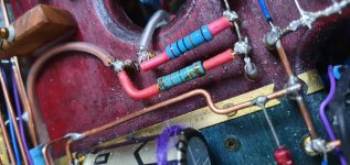
Today, I opened it up for a general inspection and noticed the 39k resistors looked scorched and instead of blue, they were cyan coloured. This is the same on both channels. Obviously something not right.
The preceeding resistors, 4.7k from the 33uf caps look fine.
Resistors are 2W
B+ is 415v
Additionally, when I did my first test voltages I measured the 220k resistor to ground, the left channel read, instantly, 220k. The right channel read 160k, and over a period of 5 minutes gradually increased to 218k. Something here too maybe someone could advise please?
Regards,
Adam
Having finished the Kegger/Blue Glow KT88SE amplifier at the weekend, I tested it and promptly installed for a listen.
I was amazed how good this amplifier sounded and had it on for around 5hrs or so.
Today, I opened it up for a general inspection and noticed the 39k resistors looked scorched and instead of blue, they were cyan coloured. This is the same on both channels. Obviously something not right.
The preceeding resistors, 4.7k from the 33uf caps look fine.
Resistors are 2W
B+ is 415v
Additionally, when I did my first test voltages I measured the 220k resistor to ground, the left channel read, instantly, 220k. The right channel read 160k, and over a period of 5 minutes gradually increased to 218k. Something here too maybe someone could advise please?
Regards,
Adam
Attachments

The 2W resistor should be enough, but you can go to 3W instead.
Don't measure resistors with the power applied. Wait until the supply is discharged,
or remove the resistor from the circuit first.
Don't measure resistors with the power applied. Wait until the supply is discharged,
or remove the resistor from the circuit first.
Last edited:
The only reason for this symptom is too high temperature of the resistor, usually caused by too high power dissipation.
Assume the voltage across the 39k resistor is 200 V.
This makes power dissipation more than 1 W, which makes 2 W resistor to run hot.
Can you measure the voltage across the 39k plate resistor ?
Assume the voltage across the 39k resistor is 200 V.
This makes power dissipation more than 1 W, which makes 2 W resistor to run hot.
Can you measure the voltage across the 39k plate resistor ?
Thanks for the reply. It is very much appreciated.
There must be something wrong somewhere though Blue Glow used 2w resistors with no problems so I'm not sure as to why mine would scorch.
I understand your comment regarding the resistor values but I would expect the same to occur on both channels, whereas in mine they differ, again, there must be a reason.
Check the voltage across the resistor, is it like the schematic?
For a 2W resistor, 1W of dissipation should be ok.
Also, mount the resistor about 1/4" above the board.
If the 220k value changes while it is out of the circuit, it is defective and should be replaced.
If it changes only when in circuit, that is normal and is due to the rest of the circuit.
For a 2W resistor, 1W of dissipation should be ok.
Also, mount the resistor about 1/4" above the board.
If the 220k value changes while it is out of the circuit, it is defective and should be replaced.
If it changes only when in circuit, that is normal and is due to the rest of the circuit.
Last edited:
Artosalo,
Thank you for your reply. The voltage leading into the resistor (b+ side) is 415v and the voltage after is 174v.
I haven't measured directly across the resistor but I can do if that is required
Thank you for your reply. The voltage leading into the resistor (b+ side) is 415v and the voltage after is 174v.
I haven't measured directly across the resistor but I can do if that is required
From voltages on the schematic those resistors dissipate about 1,15W , 3W is a better choice , or even 5W
Using a voltage drop resistor calculator and a 241v drop from 415v to 174v, with a 39k resistor equals 6ma of current and 1.47w of power consumption.
You would think 2W would still be OK?
You would think 2W would still be OK?
No, use at least 5W type.
p.s.
It's anode load resistor, so quality is important.
In this position I exclusively use good wirewound resistor, for example Mills MRA types.
p.s.
It's anode load resistor, so quality is important.
In this position I exclusively use good wirewound resistor, for example Mills MRA types.
Last edited:
Thanks Euro21, and to all that have replied.
I will order minimum 5w and once installed, I will post a final comment to close the thread.
I will order minimum 5w and once installed, I will post a final comment to close the thread.
I find it normal for cheap film resistors to change colour, especially if they get hot. I've had some turn brown but still test fine after several months.
I would go with metal oxide. Something like this: ROX5SSJ39K
or CCO(Chian Chia Elec) | CCO(Chian Chia Elec) MOF3WS-39KΩ+-5% T | Through Hole Resistors - LCSC.COM
I would go with metal oxide. Something like this: ROX5SSJ39K
or CCO(Chian Chia Elec) | CCO(Chian Chia Elec) MOF3WS-39KΩ+-5% T | Through Hole Resistors - LCSC.COM
Last edited:
Those are hard to source in the UK kodabmx.
I can get 5w, 750v Metal Oxide resistors but not 39k, so I could have a 33k and a 4k7 in series if that would is OK?
37.7k would reduce my drop from 241v to 230v and this would lift the 6n1p plate voltage from 174v to 185v. Current draw would be 6.1mA.
Power dissipation for the 1st 33k resistor, 1.25w, 0.17w for the 4k7 resistor.
Lastly, would the 200k feedback resistor need any upgrading from 2w?
Well, after a lot of searching, I managed to find the ROX resistors kodabmx recommends, albeit the 9w versions.
I also ordered the 4.7k resistors and the 200k feedback resistors, also ROX metal oxides.
I'm sure some of you will take issue of me using metal oxides for the feedback resistor, i know the power dissipation is low but my existing 2w resistors may be rated at 350v (or 500v), source doesn't know so thought to replace anyway and the ROX ones are 750v (9W).
All should be good therfore, thank you all.
I use 1/2W 2k MF for my gNFB resistor. I could probably use 1/8th watt there.
As far as the 9W MO, at least you know they should NEVER burn out, even if the tube was replaced with a short 🙂
As far as the 9W MO, at least you know they should NEVER burn out, even if the tube was replaced with a short 🙂
Additionally, when I did my first test voltages I measured the 220k resistor to ground, the left channel read, instantly, 220k. The right channel read 160k, and over a period of 5 minutes gradually increased to 218k. Something here too maybe someone could advise please?
Regards,
Adam
Bad coupling cap leaking backward to charge the B+ filter cap.
"Bad coupling cap leaking backward to charge the B+ filter cap."
Oh dear, I did burn the capacitor casing soldering an adjacent component. The burn went through the plastic insulation and I covered it with some heatshrink.
It does work albeit I think you'll recommend I replace it.
Oh dear, I did burn the capacitor casing soldering an adjacent component. The burn went through the plastic insulation and I covered it with some heatshrink.
It does work albeit I think you'll recommend I replace it.
Oh yes, that and the resistor. If the coupling cap was leaking (+) voltage to the grid, it may have also driven the output tube hard. Did you ever see the output tube red-plate? A discolored grid resistor can only come from a bad tube or bad coupling cap when used with a cathode biased output tube.
No, no red-plate, but it was only on for a few hours.
I've ordered the resistors but the scorching was definitely due to too low rating (2w whereas calculated dissipation was 1.48w) so ill re-order the caps and everything should now make sense.
Only issue now is waiting for delivery!
Thank you.
I've ordered the resistors but the scorching was definitely due to too low rating (2w whereas calculated dissipation was 1.48w) so ill re-order the caps and everything should now make sense.
Only issue now is waiting for delivery!
Thank you.
- Home
- Amplifiers
- Tubes / Valves
- KT88SE scorched resistor question.