About to start my first PP amp , and I've chosen 6L6. The data sheet shows values for 360 and 450 volts plate voltage , and the 360 volt columns have two different power "outcomes" , one 26.5 Watts and the other 18 Watts. The 26.5 W shows a lower maximum signal-plate current and a higher maximum signal-screen current and a higher plate-to-plate resistance . Is this achieved by changing the screen voltage and the tap on the transformer? I realise this is a "newbie" question , a pointer to an online tutorial would be sufficient.
Attachments
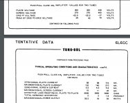
The difference comes from load resistance, i.e. from different output transformer:
- 6k6...26.5 W
- 3k8...18 W
- 6k6...26.5 W
- 3k8...18 W
As stated the differences come from the fact that the load has been changed, by using a different OPT, or changing the load or tap on the OPT. In both cases the screen grid voltage is the same, 270 volts.
The 26.5 watt case shows the conditions that the tube sees when the tubes are lightly loaded such that the maximum power is limited by voltage swing. The screen current goes up when there is a large voltage swing on the plate. This is like driving your car in 1st or second gear. Lots of RPM (voltage), but little torque (current).
The 18 watt case shows what happens when the tube is loaded heavier. It must push more current into the OPT, but sees less plate voltage swing. This is like being in 3rd or 4th gear. The tubes push more current (torque) but need less RPM (voltage).
HorsePower = torque * RPM divided by a constant.
Electrical Power = voltage * current
1 HorsePower = 746 watts.
Every mechanical or electrical engine has an operating point where it is most efficient. It generates the most POWER from it's energy source. This point depends on it's design, and what work it is doing.
The same thing happens with a tube amp. Every combination of tubes, power supply voltage, and load impedance will have exactly one optimum point of best efficiency. Some combinations will have a wide range of points with good efficiency (broad torque curve on a street driven motor), and some squeeze out maximum power optimized for one point (an all out race motor).
The two conditions shown here illustrate a pretty wide range for an all round HiFi amp (street driven motor) where the load can change with minimal effect on the amp's performance.
That OPT is just like the final drive gear box in a car (transaxle or rear differential) It has a fixed RATIO (like the gear ratio). It will turn an 8 ohm speaker into, say 5000 ohms. This ratio is fixed and does not change without changing taps.
Like all speakers, the "8 ohm" spec is an average or nominal point. The actual load impedance will change with frequency or conditions. A good amp must be able to deal with a changing load. Given a 5000 ohm OPT, the tubes will see that 5000 ohm load when the speakers are actually 8 ohms. They will see about 3800 ohms when the speakers are 6 ohms, and about 6600 ohms when the speakers are 10.5 ohms. The THD should remain under 2% for most of this range. Since speakers change over a far wider range than 6 to 10 ohms, feedback is often employed to improve the performance under changing conditions (electronic engine controls).
One can also build a "full race" motor by using the third set of conditions. Here we apply maximum voltage and current to our tubes, and tune the load for most power. The power will fall off quickly, or maximum tube ratings will be violated, on either side of this load impedance. We call these designs guitar amps. Do guitar amps eat tubes?
Tubelab_com,
Just fun for mathematicians . . .
When does the 'number' of Foot Pounds of Torque, equal the 'number' of Horsepower?
i.e. 200 foot pounds, and 200 horsepower.
It is when the rotation 'number' is approximately 5250 RPM (can be solved more accurately by those who wish to).
Just fun for mathematicians . . .
When does the 'number' of Foot Pounds of Torque, equal the 'number' of Horsepower?
i.e. 200 foot pounds, and 200 horsepower.
It is when the rotation 'number' is approximately 5250 RPM (can be solved more accurately by those who wish to).
Last edited:
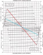
That steeper loadline is part of the spec to run a pair of 6L6s in Class AB2. If the grid drive is increased from 45 to 72 volts the audio power available is 47 watts. All in the data sheets back to the original.🙂
The spec referred to is still in Class A.
The spec referred to is still in Class A.
5250 RPM (can be solved more accurately by those who wish to).
The torque and Bhp curves must ALWAYS cross at this point, but it's only for interest, as any good old atmo race engine is gonna be up in the 10000-15000rpm range before you can blink.
However no race engine engineer is interested in horsepower, only TORQUE.
Max power is attained only where torque is dropping faster than revs are rising.
Horsepower arguments are for pubs and beer.
Torque arguments are for professionals, with engine dynos to show the work they did was valid.
I suspect it's largely the same for proper audio amplifiers.
Cathode & Anode maximum current are largely a similar function.
Get that big voltage swing, masses of current and get the dyno (scope) to measure the output into a load.
Bang lots of current into the G1 and G2 (as per tubelab with crazy drive),and you have the equivalent of turbo charging. 😀
PP Composite Loadline Example
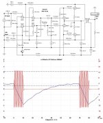
This one for PP 6V6s in Class A or Class AB2. Max power is got when the grids are driven to the extremes of the loadline. To drive into Class AB2 some power is required from the driver to supply grid current. The driver needs to be a voltage source, that means a triode. In the past that has usually meant an Interstage Transformer. More recent designs have used CF drive. See examples.🙂
This one for PP 6V6s in Class A or Class AB2. Max power is got when the grids are driven to the extremes of the loadline. To drive into Class AB2 some power is required from the driver to supply grid current. The driver needs to be a voltage source, that means a triode. In the past that has usually meant an Interstage Transformer. More recent designs have used CF drive. See examples.🙂
Attachments
Tubelab_com, Just fun for mathematicians . .
When does the 'number' of Foot Pounds of Torque, equal the 'number' of Horsepower? i.e. 200 foot pounds, and 200 horsepower.
It is when the rotation 'number' is approximately 5250 RPM (can be solved more accurately by those who wish to).
Easy number to find, no math needed. Just look at the formula to get HP from torque and RPM. H = T x rpm / 5252. The number is 5252 RPM for the US (SAE) units of measure. Some European engines use Newton Meters for torque and Kilowatts for power. Same formula, different numbers.
The torque and Bhp curves must ALWAYS cross at this point, but it's only for interest, as any good old atmo race engine is gonna be up in the 10000-15000rpm range before you can blink.
However no race engine engineer is interested in horsepower, only TORQUE.
Max power is attained only where torque is dropping faster than revs are rising. Horsepower arguments are for pubs and beer.
Someone interested in winning races needs to consider the the entire torque curve and optimize EVERYTHING so that the POWER to the wheels is constantly increasing as the vehicle goes through the gears. Simply spinning an engine to the redline then shifting gears only works if there is more torque to the wheels at the top of that gear than there will be at the point you wind up at when shifting to the next gear after the torque multiplication advantage of the lower gear is lost. For big budget road course racers this is often a different engine, transmission and rear axle ratio for each race, rules permitting. For a 1/4 mile drag racer its just "get it right one time".
Back when I did such things in the late 80's I could run a set of large tires at the drag strip and get through the traps at the top of third gear at a bit over 100 MPH. Slamming into 4th generated a faster MPH, but slower ET.
I could change tires and do a top speed run and reach 154 MPH banging into the 7200 RPM rev limiter at the top of 5th. There was exactly one tire size that would allow enough torque when shifting from 4th to 5th for the speed to continue to increase. I had to have the turbo cranked all the way up and no headwind for this to happen, otherwise there wasn't enough torque at the bottom of 5th gear to continue accelerating.
I had three different sets of tires. One for daily driving, one for the drag strip, and one for the autocross track.
Changing the tire sizes and final gear ratio is the automotive equivalent of swapping the OPT. Changing the output tap on the OPT is the audio equivalent of an old style wide ratio three speed stick shift transmission with a ration of 4:1 in first, 2:1 in second, and 1:1 in third gear.
It is possible to purposely miss-wire an OPT to obtain an overall ratio different from its original design. In my case I can use a 6600 ohm to 4-8-16 ohm OPT as a 3300 ohm OPT by connecting my 8 ohm load to the 16 ohm tap. It can also be used as a 13200 ohm OPT by connecting the 8 ohm load to the 2 ohm tap.
These is usually some loss in performance by doing this, but my budget 6600 ohm to 0-4-8-16 ohm OPT's work quite well as 3300 ohm to 0-2-4-8 ohm OPT's.
I did a similar thing with Hammond 1650N. They are 4k3 Ra-a but I wanted 2k2 so I used the 16R tap instead of 8R. It wasn't bad, but the dual Triad PT as OPT works better and costs much less. I almost always use triode connection though. The low Rp helps I think.
I almost always use triode connection though. The low Rp helps I think.
Yes, as I have explained in several threads the driving impedance that the tube / circuit presents to the OPT has a huge influence on what it does to the signal. That resonant zero formed by the leakage inductance and the winding capacitance disappears if the driving impedance is zero. A low Rp triode is the best pure tube choice. A high Gm pentode with some plate to grid feedback can often do better than some triodes.
The cheap "guitar amp" quality OPT's that I have can eat far more power over a wider frequency range when driven with a fat sweep tube with local feedback than it can when driven by an EL84 in pentode mode with GNFB.
More details are found in the post #31 and elsewhere in the Transcendar thread.
Transcendar
- Home
- Amplifiers
- Tubes / Valves
- 6L6 AB PP Data question