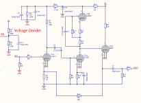
Hi, I recently bought a clone of the CAT SL-1 and this weekend I plan to start the assembly, since I did not find the schematics I decided to make it.
I would like to ask for your advice on two issues
1.- Is the diagram correct? Does it have serious bugs?
2. Is there any advice you could give me to improve it
Diagrama.jpg - Google Drive
I would like to ask for your advice on two issues
1.- Is the diagram correct? Does it have serious bugs?
2. Is there any advice you could give me to improve it
Diagrama.jpg - Google Drive
Last edited:
The 100r at the plate of the final stage is useless. The 47r loading resistor is too low for a tube. The cathode return of the last stage is missing, and the 22k is too high.
That's probably 47k, not 47R. But higher would be better, at least 100k or more.
There's no need for that first series 1k at the output.
There's no need for that first series 1k at the output.
Last edited:
The 100r at the plate of the final stage is useless. The 47r loading resistor is too low for a tube. The cathode return of the last stage is missing, and the 22k is too high.
Hi Oswaldo, can you please explain me the 22k part, in the diagram I can't see a 22k resistor, there is a .22 uf capacitor
That's probably 47k, not 47R. But higher would be better, at least 100k or more.
Hi rayma, I will order a 100k resistors to make some experiments thanks
There's no need for that first series 1k at the output.
ok, if I understand correctly I can take off the 1k resistor and connect the 10uf capacitor directly, correct?
Yes, there's no reason for that 1k. Even the second 1k has no good reason to be there.
What is the input impedance of your power amp?
What is the input impedance of your power amp?
A good case can be made for keeping the cathode stop resistor in circuit. Cathode followers have a lot of feedback, and a pole at fairly high frequency. This is equivalent to an inductive output impedance, which will try to resonate with capacitive loads. Too many cathode followers are marginally stable, and parasitics aren't unknown. The cathode stop should be mounted right at the socket pin, like a grid stop.
All good fortune,
Chris
All good fortune,
Chris
Then anything 100k up is fine for the output resistor to ground. If the last tube CF has
marginal stability, then one series 1k is fine, but it will reduce the output level by 1dB.
marginal stability, then one series 1k is fine, but it will reduce the output level by 1dB.
I'd be inclined to keep the 100R in the CF plate connection.
It can't hurt, and may reduce a tendency to ring.
It can't hurt, and may reduce a tendency to ring.
Thanks rayma, I just ordered some parts from mouser.com
This weekend I will use the board as is and the next week I will change the 100k resistor.
what should I notice with this change?
This weekend I will use the board as is and the next week I will change the 100k resistor.
what should I notice with this change?
With your 10k input impedance power amp maybe not much, but with many other amps
the bass would be deeper.
the bass would be deeper.
Hi all and thanks for all your help
I'm playing with TLSpice, I load the diagram and run some simulations
Diagram
Captura de pantalla 2021-10-06 161211.jpg - Google Drive
Frecuency Spectrum
Captura de pantalla 2021-10-06 161311.jpg - Google Drive
1khz tone input and output
Captura de pantalla 2021-10-06 161120.jpg - Google Drive
This is the first time for me with simulation so I'm exited to learning new things
A 47R resistor in the second stage is so small as to be unimportant. It could be removed (along with the coupling cap and 1M grid resistor) with no effect, or it could be increased to take some advantage of it.
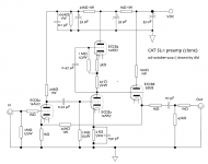
I'd be tempted to re-arrange the B+ supply so that the cathode follower was fed from the same decoupling spot as the second stage, to minimize supply interactions. (Second stage output signal is developed across the upper ECC83 half. Cathode follower input is between grid and anode. These should be connected together as well as possible.)
As rayma has pointed out, output stage cathode stop gives some loss, so could be minimized. A single resistor, mounted physically close to the socket, should do. Could be smaller value, maybe half?
This circuit has a lot of gain. 26dB at least. Do you really want this much?
All good fortune,
Chris
Edit: I see the 47R is a typo. So ignore.
Last edited:
This circuit has a lot of gain. 26dB at least. Do you really want this much?
Edit: I see the 47R is a typo. So ignore.
As I can see from the simulations you are right, it has a lot of gain
This weekend I will build the preamp and I can report my findings
I chose this board because it will be my first tube DIY project and learn some thing new.
I'd be tempted to re-arrange the B+ supply so that the cathode follower was fed from the same decoupling spot as the second stage, to minimize supply interactions. (Second stage output signal is developed across the upper ECC83 half. Cathode follower input is between grid and anode. These should be connected together as well as possible.)
As rayma has pointed out, output stage cathode stop gives some loss, so could be minimized. A single resistor, mounted physically close to the socket, should do. Could be smaller value, maybe half?
.
It would be a lot of annoyance if you could explain these points to me in more detail?
I am definitely willing to make modifications to improve the design, but I am not an expert, if you have patience I can implement them in the diagram
Thanks
- Home
- Amplifiers
- Tubes / Valves
- CAT SL-1 clone DIY project