Searching high and low for TPA3255 PCBs to integrate into a plate amplifier, I'm not really happy with what I found, especially in terms of form factor. Most PCBs have onboard heatsinks that would trap heat inside the speaker.
So here I am contemplating to roll my own. The design aim would be to have a plate amp I could use either in a 2.1 system or in a mono 3-way. This will be purely analog, no integrated DSP. As the performance in SE mode is clearly inferior, two TPA3255 will be necessary, one in stereo BTL, one in PBTL.
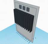
The physical design being a main consideration, I started from there. Attached is a first mockup. The base plate is a 3mm thick aluminum sheet, 37*25cm. There are only straight cuts and round holes so it can be done at home with a good saw, a file and a column drill. Attached to it is a fischer SK42/150 heatsink, 20*15cm, 25mm fins. The pcb is attached to the plate with 1.2mm thick washers, the tpa3255 thickness. The cutouts in the base plate allow the use of SMD parts under the pcb (up to 4mm thick).
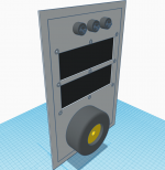
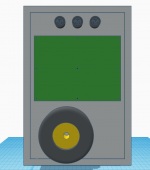
The power transformer is a toroidy 250VA/30Vac audio grade. There is ample place next to it for a pair of speakon connectors and an IEC inlet with integrated switch/fuse.
I'm slowly working on the amp schematic but before going there, I'd have a question on the TPA3255's powerpad grounding. The datasheet specifies it has to be connected to the heatsink, which itself should be grounded. If I connect all the metal parts to earth, should I also connect the TPA directly to the aluminum plate or should it be isolated ? I've found conflicting practices on the forum...
I'd gladly welcome any comments, suggestions, criticisms. I'll make the source files available when finished, even if this might be a more risky DIY endeavor than a simple lm3886.
So here I am contemplating to roll my own. The design aim would be to have a plate amp I could use either in a 2.1 system or in a mono 3-way. This will be purely analog, no integrated DSP. As the performance in SE mode is clearly inferior, two TPA3255 will be necessary, one in stereo BTL, one in PBTL.
The physical design being a main consideration, I started from there. Attached is a first mockup. The base plate is a 3mm thick aluminum sheet, 37*25cm. There are only straight cuts and round holes so it can be done at home with a good saw, a file and a column drill. Attached to it is a fischer SK42/150 heatsink, 20*15cm, 25mm fins. The pcb is attached to the plate with 1.2mm thick washers, the tpa3255 thickness. The cutouts in the base plate allow the use of SMD parts under the pcb (up to 4mm thick).
The power transformer is a toroidy 250VA/30Vac audio grade. There is ample place next to it for a pair of speakon connectors and an IEC inlet with integrated switch/fuse.
I'm slowly working on the amp schematic but before going there, I'd have a question on the TPA3255's powerpad grounding. The datasheet specifies it has to be connected to the heatsink, which itself should be grounded. If I connect all the metal parts to earth, should I also connect the TPA directly to the aluminum plate or should it be isolated ? I've found conflicting practices on the forum...
I'd gladly welcome any comments, suggestions, criticisms. I'll make the source files available when finished, even if this might be a more risky DIY endeavor than a simple lm3886.
Attachments
Yes in general the thermal design of most boards is extremely poor. Totally unusable.
On top of that most designs also use the wrong inductors as well.
I have been working on some designs myself, but because of the current chip shortages and lead times of at least 40-50 weeks for 95% of most audio IC's, these things have been postponed for the time being.
On top of that most designs also use the wrong inductors as well.
I have been working on some designs myself, but because of the current chip shortages and lead times of at least 40-50 weeks for 95% of most audio IC's, these things have been postponed for the time being.
very interesting project!
the Q1 automotive version seems to be available (on stock) from mouser in europe. any disadvantage of this version? i could not find any relevant differences, at first glance.
because of the current chip shortages and lead times of at least 40-50 weeks
the Q1 automotive version seems to be available (on stock) from mouser in europe. any disadvantage of this version? i could not find any relevant differences, at first glance.
On top of that most designs also use the wrong inductors as well.
You caught my attention there... Wrong inductors as in wrong values or wrong type/serie ?
My intention was to use 4x 1D23A inductors for the BTL section and a pair of VER2923 for the PBTL. All in 10uH. Anything wrong with these in your experience ?
You caught my attention there... Wrong inductors as in wrong values or wrong type/serie ?
My intention was to use 4x 1D23A inductors for the BTL section and a pair of VER2923 for the PBTL. All in 10uH. Anything wrong with these in your experience ?
Mostly the wrong type, a lot of them use molded inductors, which have a very soft saturation curve.
Really useful for some buck converter designs, but in audio they produce much higher distortion levels.
Next is that most use an inductor that is (way) to small.
Basically you should just have a look at the saturation curve.
The max current for audio is were the graph starts to saturate.
As a rule of thumb, I usually use 5-10% lower value as the PEAK value.
For example 100W RMS @ 4ohm -> 5A RMS.
5 * sqrt(2) = 7A.
So in this case you're looking for an inductor that saturate at 7A or better.
Thanks.
The 10µH version of the 1D23A has an Isat of 37A, the VER2393 of 30A. Both are coils designed for Class D amps. Otoh, the Coilcraft one is almost twice the price and has better DCR and heat capabilities, hence the choice of it for the PBTL section only.
The 10µH version of the 1D23A has an Isat of 37A, the VER2393 of 30A. Both are coils designed for Class D amps. Otoh, the Coilcraft one is almost twice the price and has better DCR and heat capabilities, hence the choice of it for the PBTL section only.
yeah, I guess those will be ok, but unfortunately I can't find any saturation curves.
I usually go for Sumida or so
edit; can't seem to find any high current "ferrocore" alternatives?
I usually go for Sumida or so
edit; can't seem to find any high current "ferrocore" alternatives?
Last edited:
HCI2717-100 FERROCORE - Inductor: wire | SMD; 10uH; 2.45mΩ; +-10%; 32.1A; 27.9x27.94x17.78mm | TME - Electronic components
Meanwhile they are expensive as coilcraft from Mouser
Meanwhile they are expensive as coilcraft from Mouser
Last edited:
Actually, something like a SER2918H-103KL is even cheaper direct from CoilCraft themselves. € 3.73
Only around 50+ the other one is a tiny bit cheaper.
But at 250+ the CoilCraft is cheaper again.
Rather overkill for a TPA3255 btw. (understatement)
I would go for a SMD variant btw, much easier in board design.
Only around 50+ the other one is a tiny bit cheaper.
But at 250+ the CoilCraft is cheaper again.
Rather overkill for a TPA3255 btw. (understatement)
I would go for a SMD variant btw, much easier in board design.
Last edited:
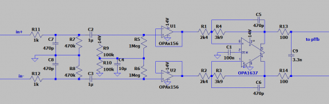
Ok, here's the input stage schematic (there will be three of these of course).
Going backwards, the TPA3255 is limited to 7Vpp at each input pin. Using the suggested pffb network, there's a 5.57dB loss, so the max voltage at the output of the "preamp" section is about 13.2Vpp. A good way to keep this in check is to simply limit the supply to the opamps. Both the opa2156 and the opa1637 swing close to the rails at the output so a 13.5V supply would be about right.
The opa2156 have fairly extensive integrated protection (diodes from input to rails and between inputs) but current must be limited to less than 10mA. That's insured by the input RC filters, at least for signals up to 24dBu (a common max in PA gear).
There is a little bit of gain in the input stage, first to get max output from a 4Vrms input (11.312Vpp) and then to add some excess gain for quiet recordings (a bit more than 3dB). The most likely source for me is a minidsp 4x10 or similar.
I'll probably draw an extension card for a 2.1 setup with standard 2Vrms SE inputs and a LR4 crossover for the sub.
Attachments
Last edited:
For what are you making this input stage exactly?
Does it need to be PRO-audio / PA input stage , pro studio environment, or just an addon for a consumer stage?
I think certain things can be simplified.
Does it need to be PRO-audio / PA input stage , pro studio environment, or just an addon for a consumer stage?
I think certain things can be simplified.
Kind of a mix... My first use will be in a hifi setup for a pair of 3-way. Source will be a digital crossover with balanced output. Second will certainly be a 2.1 smaller system, in a more typical hifi setup.
The big main simplification I can see is to remove the input buffer, pushing the resistors values around the opa1637 up. The reasons I put it in was:
- I can use smaller input caps (cheaper, physically smaller and less current available in case of a fault);
- the opa2156 is better protected against EMI and ESD and is better suited to be exposed to the outside world;
- it allows me to use lower value resistors pushing noise down. Just so that this stage isn't a bottleneck.
Clearly I'm not thinking as a manufacturer, the opa2156 is a fair bit more expensive than the opa1692 which could be a cheaper option.
The reason why I am asking, is a pro-level input stage needs a couple of extra things.
In your case, I would make it just a lot simpler.
Let me quickly draw something easy to show you what I mean (roughly)
In your case, I would make it just a lot simpler.
Let me quickly draw something easy to show you what I mean (roughly)
Ok, well this is a bit quick, but this would be roughly my approach.
I gave two different flavors, didn't put all the needed parts in both, so DON'T look at the details.
In this case it's based on symmetrical power supply, just adapt it for single supply.
Also, there are IC's that can do the task of U3/U4 (incl resistors), depending how good you want your CMRR. (something like a INA1651 , THAT128x, INA2134 etc etc)
Depending on the product, I would mostly add some diodes for EMI/ESD.
(they can also be used in the second circuit)
Typical input resistor value is mostly around 220 ohm.
Usually I would put the blocking cap right in front, but if you really want to use a single supply, you might want to move it.
In the end it doesn't really matter an awful lot, except that you have to take that into account on the max values of the other passives.
It also depends how much you want to attenuate, in that case you could do that after the last stage, do it in front, all depends.
Personally I find 24dBu a little much, even for PA gear (yes, I know in North-America it's a bit more a standard)
I usually aim for 18-20dBu.
The biggest difference between the two flavors, is that the second one doesn't have an input buffer.
I think in most cases that will be good enough, but technically it could be better.
I used both in many products for many different clients, both with success and they are very robust.
I stopped using those fully differential amplifiers.
They are great when you really have to drive a differential signal further down the line with an extremely good CMRR is needed.
More something for like an output stage or so.
FYI, they definitely would work super well also here.
They just have a tendency to be more expensive, although the opa1637 is pretty nice.
Don't bother with the 1632, they just get way to hot.
In your case, I would probably go for the easiest (and cheapest) solution.
Input impedance should be around 10-20kOhm, so it's a bit of math to get all the values right 😉
Attachments

Thanks a lot, for the suggestion and the real world experience. 🙂 I must admit I was heavily influenced for the former design by the add-on card for the reference TI board.
Ok, that would give something like this. Gain is calculated so that a 4Vrms input signal (+/- 14dBu) maxes the tpa3255 input (once the pffb is taken into account), with 3dB of excess gain. Actually a bit more than that in practice since I won't run the tpa3255 at max voltage.
I wonder if I really need the protection diodes, considering the highish input resistors. Modern opamps of choice (opa1642-1652-2156 depending on availability) are all rated for 10mA through the input pins, with integrated protection diodes.
I agree on the opa1632. I used those for I/V stages. They were already hot at +/-9V. I never tried the version with a powerpad though.
PS: + and - labels are details I didn't look at 😉
Attachments

Those diodes are more for like PRO use.
So when there are cables being used that are tens of meters long.
On the other hand, they are cheap, come in a SOT23 package (so dual).
So why not?
In your example I would skip the 220kOhm resistors I think, as well as the 1kOhm.
Also just use 4 diodes, that is enough.
For the impedance, keep in mind that seen from the input, that are in parallel.
So the impedance is around 5-6kOhm or so, which is a little low.
10uF is also a bit much for 10kOhm input impedance.
If you want to go fancy, you could make this an active 2nd order filter and diff to single amp in one as well
- Home
- Amplifiers
- Class D
- 2.1 TPA3255 plate amp design (2xBTL, 1xPBTL)