Thanks for all the info. I know way more now than I did yesterday.
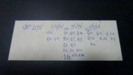
The last tech that looked at it looked for bad solders and also replaced many components. Attached is a sheet he taped to the inside which looks like a list of what he replaced.
Of the 24 Output transistors on the back 19 of them are Phase Linear so I am assuming they are original, others are 1 x Toshiba, 2 x RCA and 2 x unknown brand with stylised M.
I have been reading up about putting fuses on speakers to protect them. My Polks have fuses on the tweeters but it was the midrange that blew. More research needed.
Peter
Attachments
I would be very wary of any PL that had mix-matched output transistors. There are 5 parallel outputs (and one driver) in each group, and all 5 of the parallel units all need to be the same. The driver was originally an RCA house number and there were several versions of the “PL 909”. The only one that was worth a damn was the Fairchild version. If any of the parallel banks are mismatched, they really need to be swapped out with all the same type for reliability. The best type to use as replacement is the MJ21194 (or 21196), for both driver and output. 15024 is good too, and is in fact better in the PL400. The RCA drivers are fine if they are still good, but don’t use a PL909 as a driver. Personally, I would change out any PL909 that’s not the Fairchild type (the “F” logo). The others were all ticking time bombs. RCA1B05 are ok for outputs, if your particular amp had them. I still have a PL400 with them in one channel. There are *no* suitable Toshiba parts for output or driver for the 700. The 2SD424 is fine in the 400 but not the 700. It is only rated 180 volts and the typical is only good for 220. If your 700 has a high line voltage they will blow.
Attached is a photo of the output transistors.
From what you guys tell me I need to replace them all and go through the unit joint by joint and possibly replace everything else as well. Paying a pro to do this would cost me more than the unit is worth and even then it might not fix my problem.
Seems the best use for it is a scultpture for my mantle unless I can find a friend who is into electronics to have a go at it for me as a fun project.
Attachments

Or you could sell it to a person who made a good offer.
If you feel like, put it up on that forum.
Just how big is your listening area?
For a replacement, how many watts worth of amplifier would be needed?
If you feel like, put it up on that forum.
Just how big is your listening area?
For a replacement, how many watts worth of amplifier would be needed?
You’ve got to fix your problem first. That’s unrelated to what type of output transistors you have. The bottom row are the drivers. One type in one channel one in the other. No problem at all with that. Those Motorola SJ2741 are MJ410’s, and those RCA’s are similar. That 2SD424 is worrisome, because it is underrated for voltage and mismatched with the rest of the bank. It could hog current and get over stressed, or sit there and not take any of the load. But the other problem s running a D424 on +/-110 volts. They are very rugged, but it is playing with fire unless you screen it for breakdown voltage and be sure it can block the entire supply voltage plus margin. The combination just isn’t safe. I would have swapped all 5 of those out for MJL21194, or maybe the entire channel. Then you would have 4 or 9 PL909’s if you blow any in the other channel. The X PL909 isn’t very rugged compared to the F PL909 or the modern On Semi parts, but it you’re not blowing them under you’re usage they may be ok especially if you have extras on hand. But don’t even fool around with any of that till you find and correct whatever bad connection is causing your immediate issue.
Looking doesn't find good appearing bad solder joints. I've seen some beautiful bandits in Peavey 90's products. You've got to push on every joint with a stick with the power on, while listening for pop or funny noise.The last tech that looked at it looked for bad solders and also replaced many components.
Peter
Tech who quoted replacing every part was quoting enough time to pay for the labor to do this job. Not every part needs replaced, but his time is worth $$ per hour. Shop techs are used to replacing output transistor sets on bar band units where the wiring was shorted on stage, not finding DC on speaker bad joints.
You're not blowing output transistors. your installed fleet is not ideal but that problem can be put off as wgski said. Unless the low voltage toshiba part is breaking down ittermittantly. MJ21193 or MJ15024 are so more powerful (soa) than these 1975? parts you could get away with 3 or 4 instead of 5 in parallel.
If problem is a bad weld inside a part instead of a bad solder joint outside, then yes, you may find an area where the amp goes to DC with a hair dryer or a circuit cool sprayer, without finding the exact part coming loose inside. In that case you replace all the parts in that area. Then cook for hours through the DC block capacitors listening all the time to see if problem re-occurs.
Oh, on the every part front, 1975 electrolytic caps can be as bad as 1975 tires. They are sometimes sealed with really cheap rubber. ESR test will reveal if it is necessary, but the ESR meter is $120 US and the set of caps is about $70 or less. Check or replace those before starting out on bad joint patrol.
And really, nobody else is going to spend the time to gild this pig (find the problem) except you. It is not worth it at $80 or $100 an hour. Phase Linears are not highly respected, just interesting. The competition at the time, Crown DC300, was designed to produce DC out on hydraulic valve solenoids & diesel motor throttles & the like. Death to speakers if the DC balance pot wiper cut loose. People used DC300 onstage because they held up better than the competition (this). Pink Floyd was using stacks of vacuum tube amps for their wall of sound, because they held up better than SS amps at the time.
Last edited:
Hmmm... looks super toasted to me, and like @MOER said, it's a complete and total turd of an amplifier. I'd be happy to take it off your hands so you don't have to landfill it. I'll even be super generous pay you $20 to ship it to Wisconsin! 😀
I might get a set of expendable speakers and run it for a few days. You never know, having a rest for 20 years might have cured it.
Also, the problem with selling it is that I am in Australia. Postage to USA would be more expensive than the amp. If I was in USA I would be getting it fixed, plenty of expertise over there.
Also, the problem with selling it is that I am in Australia. Postage to USA would be more expensive than the amp. If I was in USA I would be getting it fixed, plenty of expertise over there.
First basic question, do both channels behave badly, or is it just one side?
Second question, what is the AC mains voltage?
Second question, what is the AC mains voltage?
Next up, put a meter on the output and see if the output voltage spike is positive or negative. You might want to use a light bulb as the load for testing.
Also did you measure the mains voltage?
Also did you measure the mains voltage?
Everything in Australia 240v. I haven't measured it.
My multimeter gave up the ghost and we are in COVID lockdown so it may be a few weeks before I can do any testing.
I will get back when I can and find out what output voltage you mean.
My multimeter gave up the ghost and we are in COVID lockdown so it may be a few weeks before I can do any testing.
I will get back when I can and find out what output voltage you mean.
Analog meter for detecting music, ($40) DVM for detecting +-DC. Or $180 Fluke RMS DVM, which can't even see oscillation >7000 hz, which might be happening here. Or scope _+ 10 x probes.
When ordering meter, don't forget to order 2 big e-caps to block DC to the speaker while testing. 2 4700 uf, or 5600 uf or 10000 uf, or even 2200uf. You connect the minuses of the caps and connect the plusses to the speaker jack and the speaker.
I'd get the 4 rail caps, 5600 uf, at the same time. Calender says your old ones are probably dried up. Wgski warned about the beeping. Read dimensions @ vendor, caps can be too tall or too fat or have wrong pin spacing. Snap in caps are much cheaper than screw terminal caps. Buy service life rating >3000 hours, you don't want to replace them again in 2 years.
Also in the same package, alligator clips. Also soldering iron and 60/40 or 63/35 rosin core solder. People say hakko vari-temp iron is okay. Get a chisel tip 2 or 3 mm, they make for faster work on medium size parts than the pointy tip they come with. Fast work keeps the pcb lands from coming unglued. Also a solder sucker bulb, or spring sucker, or solder wick.
Also 1/8" stereo phone plug to dual RCA plug adapter to put battery radio signal in the amp. Earphones to check you are tuned on station. battery radio if you don't have one. Or $100 signal generator.
Voltage of DC out can wait IMHO until it stops popping & beeping. Final check is DC out <200 mv, along with idle current through output transistor emmiter resistors.
Basic training for newbies: never use 2 hands with the power on or until rail caps discharge afterwards. Voltage >25 across your heart can stop it. Connect negative of DVM with aligator clip lead to speaker ground, or common connection of the 2 rail caps (analog ground). Shock to 1 hand non-dangerous except the AC mains area, stay away from that area power on.
Don't wear jewelry on hands, wrists, or neck. 1 v through a ring at high amperage can burn your flesh to charcoal.
Wear safety glasses (or at our age, reading glasses). Don't work alone or distracted by conversation or entertainment.
Last edited:
on ebay you can buy 4 Ohm or 8 Ohm 100 watt resistors for a couple of dollars. Bolt them to a heat sink. Hook them up series and or parallel to give you 8 Ohms at 400 watts or so. Connect them to a 0.1 or 0.2 Ohm resistor. Connect a cheap speaker in parallel with the 0.1 or 0.2Ohm resistor. You can now have the amp play music or just sit there while you wait for the problem to show up and not blow up another speaker.
I made a box with 8 4Ohm 100 watt resistors and 4 8 Ohm 100 Watt resistors. I connected each end of the resistors to some Female banana sockets. I can series parallel the resistors with jumpers to give me any combination of 1 Ohm to 32 Ohms per channel.
I made a box with 8 4Ohm 100 watt resistors and 4 8 Ohm 100 Watt resistors. I connected each end of the resistors to some Female banana sockets. I can series parallel the resistors with jumpers to give me any combination of 1 Ohm to 32 Ohms per channel.
I'd get the 4 rail caps, 5600 uf, at the same time. Calender says your old ones are probably dried up. Wgski warned about the beeping. Read dimensions @ vendor, caps can be too tall or too fat or have wrong pin spacing. Snap in caps are much cheaper than screw terminal caps. Buy service life rating >3000 hours, you don't want to replace them again in 2 years.
Voltage of DC out can wait IMHO until it stops popping & beeping. Final check is DC out <200 mv, along with idle current through output transistor emmiter resistors.
The original caps are long and skinny, but it should be possible to use snap-ins with wire leads added to them. That might be the only thing that will *fit* as you may be stuck using 200 volt caps. The originals will be 125, which is not common anymore. 200 volt computer grade types are usually too big around and 100 volt isn’t enough. They may not be bad, but the fact that it makes a loud buzz when putting DC to the speaker suggests they could be. Once you get the amp working run a short duration sine wave test into an 8 ohm dummy load. If you don’t get rated power the caps need replacing. If you do, they don’t - yet. If you blow XPL909’s with a 5 second full power test at 8 ohms that will tell you they’re not safe enough to use. FPL909’s, RCA1B05’s, 2SD555’s or MJ15024/21194 *will* take that, no if’s ands or buts.
This particular amp (and many like it) have “strange” requirements for setting output transistor bias. You don’t want quiescent current in the outputs, just the drivers. It is supposed to be set for 350 mV from base to emitter of one of the output transistors. That results in zero bias in the outputs, and 60 mA bias in the drivers. The quasi-comp triple is often unstable (it can oscillate) at a few mA of quiescent current in the outputs when running at this high a Vce. They are stable at no bias, and become stable again at high bias (but will generate too much heat that way). Newer versions of the Series 2 switched to full complementary outputs when the MJ15025 was invented. The full comp version was better, because the output stage is locally stable at ANY bias. You can set those to 3 to 10mA per output transistor, which is a good compromise between crossover distortion and heat generation. Most modern PA amps set it there. But with the original quasi-comp stage that almost guarantees oscillation.
I notice on the schematic that there is no build-out inductor + resistor, which means the stability will depend on speakers and speaker cable. Your feedback may have killed the (2x10 Ohm-1W) resistors in the Zobel network leaving the amp even more unstable. Years ago (~1980) I fought with, I think 400s, which used an op-amp in the front end and the only solution I found then was adding local feedback around the op-amp. But we had no SPICE then and I have learned a lot since then. If I owned one today, I would test modifications in SPICE until it was rock solid and then try it on the hardware. I might just rip out the PCB and replace it with a modern ~blameless circuit. That could be complimentary if you care to spend money on new output transistors but I think it's possible to make a stable quasi amp. Adding buck converters, you could go for class-H for better efficiency, or even class-D. The point would be to re-use the expensive power supply and chassis and get new relatively cheap (today) silicon. Unfortunately, those capable of doing that may not be interested in doing it.
The frequency compensation in the Series 2 with the op amp was dead wrong, that’s one reason they tended to oscillate. Excessive phase lead was used - the amount needs to be REDUCED. Local feedback on the op amp was one method of fixing it - there are others. The old version had a more stable global feedback loop. The local output stage oscillations were entirely separate, and affected all of the quasi comp versions. Especially when XPL909’s were used. That transistor is actually a *darlington* switching transistor, with the base-emitter of the internal driver wire-bonded over to make it look like a normal transistor. The extra parasitics were not good for stability, and THE reason the XPL909 cannot be used in the driver position.
Why all the fuss??? (move on)
I saw W A Y too many of these in the shop, to ever think about owning
a Flame Linear 400 or 700. Hitachi MOSFETS based amps
have never let me down.
There are simply *too many great high power / performance options Hypex / ICE. etc.
to fuss with a complete rebuild (an imperative) for ALL VINTAGE GEAR.
*this is without exception. *What Bill said...
Only a very patient and skilled technician should (own?) be inside an amp like that.
I have been building, and working on amps for 40 years,
I would not touch it.
Sorry to be so honest, realistic.
Ozark
Hey, it’s a great case and heatsink, it would make a real cool retro looking modern amp. Your biggest expense in a new build is the case and transformer, if you could reuse those half of your cost is covered.
Bill
Bill
Last edited:
- Home
- Amplifiers
- Solid State
- Phase Linear 700B burns speakers