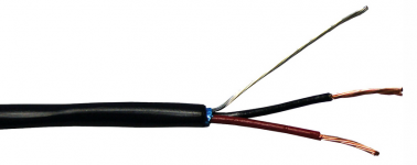
Is the pictured type of mic cable unsuitable for wiring the input signals in a power amplifier chassis? It is called "Rapco CM Rated Installation Grade Mic Cable":
Rapco CM Rated Installation Grade Mic Cable | Musician's Friend
Such as wiring from the RCA to the potentiometer board? And then the potentiometer board to the power amplifier boards?
I ask primarily due to the foil shield type construction. Is the resistance too high? Or the shielding (foil) not optimal/not suitable? From reading the following link (slide 31) should I purchase a different type with a heavy braided copper shield instead?
http://hifisonix.com/wordpress/wp-content/uploads/2019/02/Ground-Loops.pdf
I ask since I am trying to reduce hum (and a THD increase) that occurs when both inputs are wired to the amplifier boards in a stereo configuration. I think a loop is occurring as per slide 36 of the hifisonix document. I wonder if it is worth trying to reduce the resistance in the loop (with lower resistance interconnect) or whether I should simply switch to dual power transformers and dual rectifier/filter boards or even a mono-block configuration to avoid the loop.
Here are measurements with and without the suspected ground loop:
https://www.diyaudio.com/forums/sof...stortion-measurements-rew-96.html#post6781170
Attachments
I might try it but I would need to cut at least two PCB traces on each of the amplifier PCB (for the input and the feedback connections to the PCB star ground). Then I would need to join those two together and then connect them through the hum breaker resistor.
I guess I would prefer to try a couple interconnect/wiring options before I start cutting the PCBs.
I guess I would prefer to try a couple interconnect/wiring options before I start cutting the PCBs.
Attachments
Hi
check if your Amplifier inside uses Star Grounding.. All GND Cables to one CASE GROUND. the PCB or input ground lift of the CASE if this is connected to the case..
I suppose the Hum occurs as soon you plug in the second RCA. Also lift off the Speaker GND off the case if this is connected to the CASE GND and then it actually should work just good..
I use similar cable as you of the brand whirlwind.. but only a single wire inside. but you could twist two of them together and the left over connect to GND.. this should work..
Hope this helps..
I think there are two issues.
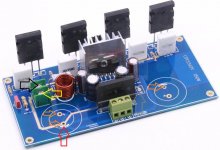
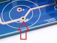
One is that the amplifier PCB (and there are two in the chassis) has a star ground layout in each of the two PCB. The star ground is around one of the thru holes for the snap-in filter capacitors.
Another is that the amplifier (stereo) has one power transformer and one filter/rectifier board. So a ground loop is formed. The first connection is from the amplifier PCB (two of them) to the ground terminals on the filter/rectifier board. The second connection is from the two inputs (which are physically separate on two different amplifier PCB) that are routed through the chassis and then joined together (soldered together) on the potentiometer PCB.
Without adding a second independent power transformer and rectifier/filter PCB I am not sure how to prevent this loop.
The HRB (hum breaker resistor) is possibly a mitigating solution. Reducing the interconnect resistance might help.
The wire is fine. Cheap and un-sexy, but fine.
Hum problems inside a chassis are almost never due to the wire-type, but connection details.
Hum problems inside a chassis are almost never due to the wire-type, but connection details.
I tried using twisted pair (home made) from 22 AWG stranded copper (tightly twisted with a power drill) and the results were similar. So that is not the problem. THD was improved when I replaced the wire and removed the potentiometer board but that is convoluted by several changes plus amplitude is now controlled by the E-MU 0404 USB output level (REW generator setting).
I agree with 99%+ certainly that this is a connection issue caused by how the grounding is forced to be connected. (Due to PCB design and a single power supply.) However apart from a mono-block or two separate power supplies I am not sure how to solve the problem with the two amplifier PCB as designed. As a mono-block it works very well.
Below is first one side (only) connected (from RCA inputs terminals to amplifier) with tightly twisted pair. The second is with both connected. The degradation is clear.
Attachments
Last edited:
Below is with cutting the traces (for the input and feedback network) and inserting a 10 Ohm Hum Breaker Resistor into the tested side of the amplifier.
1. Without Hum Breaker Resistor. Both side twisted pair for input connection.
2. With Hum Breaker Resistor. Both side twisted pair for input connection.
3. With Hum Breaker Resistor. Other side input disconnected.
"So That Did Not Work"
Unless someone has another suggestion I think dual mono-blocks will be the answer next week.
Attachments
-
 8Vrms Near Side Only Near Side Connected With Tight Twisted Pair Near Side 10 Ohm Hum Breaker Re.png171.5 KB · Views: 61
 -
 8Vrms Near Side Both Sides Connected With Tight Twisted Pair Near Side 10 Ohm Hum Breaker Resist.png155 KB · Views: 58
 -
 8Vrms Near Side Both Sides Connected With Tight Twisted Pair.png166.3 KB · Views: 74
These Test look good. What are you trying to achieve?
BTW the first measurement is the best..
Show a Measure when both channels are connected..
Again, never mind if you have one or two Transformers, dual bridge or even Quad bride, it it loops then it loops. The reason because the HUM takes the most easiest way back.
What happen if you connect the input JACK RCA I think connect to GND?
Do you hear any hum on the speakers?
I might try it but I would need to cut at least two PCB traces on each of the amplifier PCB (for the input and the feedback connections to the PCB star ground). Then I would need to join those two together and then connect them through the hum breaker resistor.
I guess I would prefer to try a couple interconnect/wiring options before I start cutting the PCBs.
PCB isn't star grounding. this is because that amplifier uses two RAIL VOLTAGES
PCB is single Point Grounding. So connect the ground where it's suppose to be the same for Rail Voltages..
Prior to anything connect the RAILS on the SPOT where it should be and then I think it will be better..
Why do you connect the power on if its Transistor on Collector and Emitter if it is Mosfet On Drain and Source instead there on POWER CONNECTOR?
Connect it as it is designed, and then try again.
Nothing more to say.
Last edited:
I did not connect the power directly to the power transistors. It is connected (soldered) to the snap-in filter capacitors on the underside of the PCB. That is where the PCB trace goes to. (The two large power filter capacitors.)Why do you connect the power on if its Transistor on Collector and Emitter if it is Mosfet On Drain and Source instead there on POWER CONNECTOR?
Also the screw terminals that ship with the kit do not fit through the thru holes.
The clip leads on the transistors are just volt meters monitoring the bias.
Because there are two power connectors (one on each PCB) that go to a rectifier (on each PCB). So a previous buyer said that the rectifier that close to the uPC1342V was causing hum. (I don't know if that is correct.)Connect it as it is designed, and then try again.
Nothing more to say.
If I had two transformer secondaries I could connect it as designed (with one secondary going to the connector on the first board and the other going to the second board power connector).
Since my chassis came with a transformer with one secondary (and the previous buyer commenting that the rectifier was too close to the uPC1342V input terminals) I connected my single power transformer to an external rectifier/filter board. Then to the thru holes/legs of the snap in filter capacitors on each of the two uPC1342V boards.
Are you suggesting that I should install the two bridge rectifiers (one on each amplifier PCB) and connect the single center tapped secondary to both of the boards with three Y shaped wires?
Last edited:
If I talk about lifting input ground of the CASE, then I mean on the CHASSIS SIDE, if the input connector is connected direct to the chassis.. this is a no go
The same counts for the NEGATIVE SPEAKER TERMINAL
I did no where talk about that you modify your PCB..
But I sincerely start to question your understanding of all the where about.
Again, first to come first
Connect the amp as it was designed for. and then check it, and I think you might be positively surprised how good it is in fact..
Since your board are SINGLE BOARDS with everything what it takes to run them, why you do not just run them that way. you have on each board a Rectifier Bridge, and also the caps for it.. connect the transformers and keep input output negative connectors of the chassis.. that's all what I try to tell you.. no need to have an extra PSU Board for each amp.
This is all I can help you, and again, your cables are OK.
The terminals have always been insulated from the chassis. (Input and output.)Since your board are SINGLE BOARDS with everything what it takes to run them, why you do not just run them that way. you have on each board a Rectifier Bridge, and also the caps for it.. connect the transformers and keep input output negative connectors of the chassis.. that's all what I try to tell you.. no need to have an extra PSU Board for each amp.
As stated there is one transformer and two boards. What I was trying to achieve was good performance with one transformer and two boards, not with two transformers. I already know the problem does not exist with two transformers.
It appears that after designing this uPC1342V board that the same designer designed two stereo boards (one with 2x1342V and one with the uPC2581V) that have careful power supply and grounding layout that supports stereo operation with one transformer and one power supply. My board, however, is a higher power single channel board that appears to be best run as a mono-block unless there are two transformers or at least two secondaries on one transformer.
What's the VAC of your Transformer I look at it in the picture it is not that large.. using a transformer underrated of the power it should deliver but it does not or can not, will ultimate HUM, but it will not create a ground loop..
And Ground loop will only occur when both RCA Jacks or Sleeve Jacks are inserted and as soon as GND of the MALE JACK hits the GND of the Female Jack on the Chassis...
Have you measured the NEGATIVE Connection side with unsoldered CABLES against the CHASSIS.. It has to show no resistance *infinite* at all between these point, when you measure OHMS.. if there is resistance then you need to take care of that problem.. only then you can be sure that the Connector to the chassis does not create a GND LOOP..
I think that it don't matters what kind of IC or transistor is used in regulation of the AC POWER TO DC.. as long the follow up has been connected correctly
it's a wiring thing..
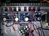
BTW I see the transistors, have no Silicone heat sink compound or grease between them and the MICA and the Aluminum..
When turning up that Amp you run in trouble because overheating or at least unnecessary heating will occur..
May someone else know more about this phenomena..
And Ground loop will only occur when both RCA Jacks or Sleeve Jacks are inserted and as soon as GND of the MALE JACK hits the GND of the Female Jack on the Chassis...
Have you measured the NEGATIVE Connection side with unsoldered CABLES against the CHASSIS.. It has to show no resistance *infinite* at all between these point, when you measure OHMS.. if there is resistance then you need to take care of that problem.. only then you can be sure that the Connector to the chassis does not create a GND LOOP..
I think that it don't matters what kind of IC or transistor is used in regulation of the AC POWER TO DC.. as long the follow up has been connected correctly
it's a wiring thing..
BTW I see the transistors, have no Silicone heat sink compound or grease between them and the MICA and the Aluminum..
When turning up that Amp you run in trouble because overheating or at least unnecessary heating will occur..
May someone else know more about this phenomena..
I am using the Thermally Conductive Silicone Pads that came with the kit. (Not the mica type.) My understanding is that the silicone pads are not used with grease. I do have an IR thermometer and the temperature of transistor molding compound directly above the large output stage die indicates a good thermal resistance.BTW I see the transistors, have no Silicone heat sink compound or grease between them and the MICA and the Aluminum..
The transformer that is currently be used (which is outside of the chassis) is rated 370VA from an Onkyo home theater receiver.What's the VAC of your Transformer I look at it in the picture it is not that large.. using a transformer underrated of the power it should deliver but it does not or can not, will ultimate HUM, but it will not create a ground loop..
The transformer that is inside the chassis is from a 200W rated stereo receiver. It has a weight and dimensions very similar to the Onkyo transformer. The label on the chassis suggests 300VA.
I just measured that with a voltmeter and... ...it read connected (which I was not expecting). So I disconnected the input board and yes it is just touching/rubbing against the chassis. I have a different type of RCA connector which I will try next which definitely should not do that. I will go test it shortly.Have you measured the NEGATIVE Connection side with unsoldered CABLES against the CHASSIS.. It has to show no resistance *infinite* at all between these point, when you measure OHMS.. if there is resistance then you need to take care of that problem.. only then you can be sure that the Connector to the chassis does not create a GND LOOP..
Last edited:
transformer should be at least 500VAC../ amp
What's the Rail Rating given by the designer VRail+ Vrail - ???
Measure it and when the Amp is switched off and then measure when Idle and then on 50% Load, so you can calculate how much it drops on full load. and how much it differs from the designers Value.
About these Thermal Silicone Pads, OK but I would use Mica with Silicone Heat transfer compound.. Measure the heat on top of the transistor not only on the heat sink, Measure that black square where the Label is printed on .. you will be surprised..
No Change With New (Definitely Insulated) Input Jacks
Unfortunately there is no improvement with new input jacks which are definitely insulated from the chassis.
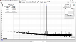
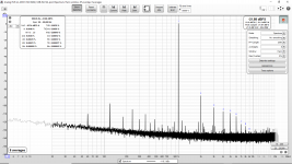
The first attached image is:
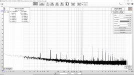
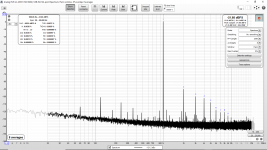
The second attached image is:
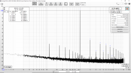
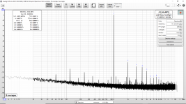
The third attached image is:
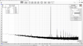
The fourth attached image is:
So my conclusion remains the same. There is a loop forming due to the two inputs grounds being connected. It makes no difference whether they are connected at the chassis or at the signal source. Either produce the degradation.
Insulating the input jacks did not change the measurements. (The old connectors were believed to be insulated but they appear to have shifted/moved over time and rubbed against the chassis. The newly installed jacks can not do that.)
The type of loop I am describing is (I believe) the cross channel current loop described on slide #34 of the following hifisonix document:
http://hifisonix.com/wordpress/wp-content/uploads/2019/02/Ground-Loops.pdf
I believe that I have tried all of the possible solutions. At this point either I use two chassis and wire as two mono-blocks or I could get one of the stereo uPC1342V or uPC2581V boards that have the appropriate grounding and layout.
Since the performance of this uPC1342V board is very good I think my best solution is to simply put one in each chassis as a mono-block. I do not want to change the transformer (to one with two secondaries) and I can not fit a second transformer in this chassis.
Unfortunately there is no improvement with new input jacks which are definitely insulated from the chassis.
The first attached image is:
- New RCA jacks (definitely insulated from the chassis)
- Only one channel connected to the source (battery power E-MU 0404 USB)
- Very good THD and mains/power line harmonics
The second attached image is:
- New RCA jacks (definitely insulated from the chassis)
- Both channels connected to the source (battery power E-MU 0404 USB)
- Unfortunately the THD and mains/power line harmonics jump up/degrade exactly like before
The third attached image is:
- New RCA jacks (definitely insulated from the chassis)
- Both channels connected to the source (battery power E-MU 0404 USB)
- The grounds/shields of the two new RCA input jacks are still insulated from the chassis but are connected together inside the chassis
- Unfortunately the THD and mains/power line harmonics jump up/degrade exactly like before
The fourth attached image is:
- New RCA jacks (definitely insulated from the chassis)
- Only one channel connected to the source (battery power E-MU 0404 USB)
- The grounds/shields of the two new RCA input jacks are still insulated from the chassis but are connected together inside the chassis
- Unfortunately the THD and mains/power line harmonics jump up/degrade exactly like before
So my conclusion remains the same. There is a loop forming due to the two inputs grounds being connected. It makes no difference whether they are connected at the chassis or at the signal source. Either produce the degradation.
Insulating the input jacks did not change the measurements. (The old connectors were believed to be insulated but they appear to have shifted/moved over time and rubbed against the chassis. The newly installed jacks can not do that.)
The type of loop I am describing is (I believe) the cross channel current loop described on slide #34 of the following hifisonix document:
http://hifisonix.com/wordpress/wp-content/uploads/2019/02/Ground-Loops.pdf
I believe that I have tried all of the possible solutions. At this point either I use two chassis and wire as two mono-blocks or I could get one of the stereo uPC1342V or uPC2581V boards that have the appropriate grounding and layout.
Since the performance of this uPC1342V board is very good I think my best solution is to simply put one in each chassis as a mono-block. I do not want to change the transformer (to one with two secondaries) and I can not fit a second transformer in this chassis.
Attachments
-
 8Vrms Near Channel Only Connected.png164 KB · Views: 86
 -
 8Vrms Near Channel Both Channels Connected.png153.2 KB · Views: 90
 -
 8Vrms Near Channel Both Channels Connected Laptop Battery Short Two RCA Ground At Chassis.png152.7 KB · Views: 87
 -
 8Vrms Near Channel Only Connected Laptop Battery Short Two RCA Ground At Chassis.png148.2 KB · Views: 94
transformer should be at least 500VAC../ amp
What's the Rail Rating given by the designer VRail+ Vrail - ???
Measure it and when the Amp is switched off and then measure when Idle and then on 50% Load, so you can calculate how much it drops on full load. and how much it differs from the designers Value.
About these Thermal Silicone Pads, OK but I would use Mica with Silicone Heat transfer compound.. Measure the heat on top of the transistor not only on the heat sink, Measure that black square where the Label is printed on .. you will be surprised..
I did point the IR thermometer on the top of the transistor (label area) directly above the location of the transistor die inside the molding compound.
The designer provided the following:
One of my transformers is AC 2x32V and the other is AC 2x35V. The speakers are 4 Ohm. My test load is two parallel EBG UXP/300 10 Ohm resistors for a 5 Ohm test load. I also have two other 4 Ohm test loads made from 100W aluminum cased "non-inductive" wire wound resistors.Core circuit: NEC company following the excellent performance of broadband low distortion 50w drive circuit UPC1225H, in order to meet the requirements of high power has introduced a new generation of audio driver IC - UPC1342V, the IC in addition to all the advantages of UPC1225H and basically the same external circuit , The output voltage deviation is smaller (± 5mV), the voltage to adapt to a wider range (± 20 ~ ± 70V), to promote the power more abundant
Output power: According to the different power supply voltage, speaker impedance of the different output power 20-150w; when AC35v power supply, you can output 130w * 2/8 ohms, 200w * 2/4 ohm
Last edited:
Unfortunately there is no improvement with new input jacks which are definitely insulated from the chassis.
The first attached image is:
- New RCA jacks (definitely insulated from the chassis)
- Only one channel connected to the source (battery power E-MU 0404 USB)
- Very good THD and mains/power line harmonics
The second attached image is:
- New RCA jacks (definitely insulated from the chassis)
- Both channels connected to the source (battery power E-MU 0404 USB)
- Unfortunately the THD and mains/power line harmonics jump up/degrade exactly like before
The third attached image is:
- New RCA jacks (definitely insulated from the chassis)
- Both channels connected to the source (battery power E-MU 0404 USB)
- The grounds/shields of the two new RCA input jacks are still insulated from the chassis but are connected together inside the chassis
- Unfortunately the THD and mains/power line harmonics jump up/degrade exactly like before
The fourth attached image is:
- New RCA jacks (definitely insulated from the chassis)
- Only one channel connected to the source (battery power E-MU 0404 USB)
- The grounds/shields of the two new RCA input jacks are still insulated from the chassis but are connected together inside the chassis
- Unfortunately the THD and mains/power line harmonics jump up/degrade exactly like before
So my conclusion remains the same. There is a loop forming due to the two inputs grounds being connected. It makes no difference whether they are connected at the chassis or at the signal source. Either produce the degradation.
Insulating the input jacks did not change the measurements. (The old connectors were believed to be insulated but they appear to have shifted/moved over time and rubbed against the chassis. The newly installed jacks can not do that.)
The type of loop I am describing is (I believe) the cross channel current loop described on slide #34 of the following hifisonix document:
http://hifisonix.com/wordpress/wp-content/uploads/2019/02/Ground-Loops.pdf
I believe that I have tried all of the possible solutions. At this point either I use two chassis and wire as two mono-blocks or I could get one of the stereo uPC1342V or uPC2581V boards that have the appropriate grounding and layout.
Since the performance of this uPC1342V board is very good I think my best solution is to simply put one in each chassis as a mono-block. I do not want to change the transformer (to one with two secondaries) and I can not fit a second transformer in this chassis.
My start question comes back: what are you trying to achieve ?
this you will not even hear on the headphones.
Sure, however after all the effort I put into the ES9038Q2M and my own 4-layer layout PCM1794A DAC I just "would like" the following amplifier to be as good as possible. Also I see how good the uPC1342V can be (with two pairs of Toshiba 5200/1943 outputs) and I don't want to compromise the performance.
After the effort to layout and assemble the PCM1794A (and measure performance with about a dozen op-amps from NE5532 to NJM2068 to NJM4580 to OPA1612 to OPA2228) I just don't like seeing the THD and mains/line harmonics jump up.
It is a just a personal interest in making it the best I can with the available supplies and tools.
Honestly I think the performance is incredible for something built with a kit sold for $13 each (plus shipping) on AliExpress and then using a recycled dead stereo chassis, power transformer and salvaged filter capacitors.
Last edited:
- Home
- Design & Build
- Construction Tips
- Is This Mic Cable Unsuited For Wiring The Inputs Signals In A Power Amplifier?