The leakage cap I have ordered before from US, but made in France I returned all, it measured a fixed resistance up to only a few Megs.
OK. A leakage resistance of a few Megs is not uncommon. But a coupling capacitor going 12K is not a very common problem as far as I know. And how you calculated the 12K is still unclear to me.
Addition: The question remains how the 6C33C-B survived the +80 V on its grid. I think it couldn't. So if it did not die, than the voltage on its grid could not have been +80 V unless the 6C33C-B itself is the root of the problem (like Mona already suggested). For me I think that the most likely explanation is still that the measurement of +80 V at the cathode of the driver must have been wrong.
Last edited:
12K is the imagined value shunting the tube for 5678 to get 80V in cathode. It's one of potential source of positive voltage appeared in cathode,
My calculation is 210K shunting the coupling cap this gives about 76V on grid, and 80V on cathode, 200V plate on previous section. I hope I made it clear by now, if not show where you find that hard to figure out?. Since this involved active device try to use some software tool is preferred. Btw a few Meg measured on DMM could be a few hundred K under high voltage conditions don't think so??
And post #1 I heard him said no tube as measurement taken place, that is why I ask for measurement under fully on condition with tubes. Maybe OP hasn't plug in 6c33c knowing that the bias isn't right.
Last edited:
I have built my first ever tube amp, ...
Isn't the moral of the story here that an uncomon design that has directly coupled stages is not a good choice for a first time build?
Wouldn't the best course of action be to look at the parts on hand, and come up with a simpler design. Debug that, then move on to soething more esoteric.
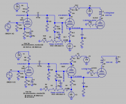
Possible. Cathode 1.1V/74V when B+ off/onOther possibility, the grid and cathode 6C33 are cross coupled.
Mona
OP mentioned it was -1.5V when heater and bias are on (no B+) and 80V when B+ is on.
Attachments
Last edited:
But what about the 6C33C-B? You wrote that you had all the tubes in. If there really was +70 V on the grid of the 6C33C-B than you must have noticed that right away.
Addition: In itself, the voltage at the cathode could rise to 70 V if the current through the 27K cathode resistor is high enough. With -180 V the current would than have to be: I = V / R = (180 + 70) / 27K = 9.26 mA. I write 'in itself' because such a large current is difficult to combine with the way the driver seems to be biased. And again, I would expect the 6C33C-B starting to die right away with +70 V on its grid.
So I thought that I would notice it right away, but there was nothing weird happening, and once I had reading of +70 I turned everything down right away.
What would cause the cathode to draw more current than it should?
sorry for the late reply, I am preparing to move, so a lot of work around the house...
The second grid of the 5687 was -85ish in both cases with and without B+.
I did check the solder joints, and cleaned the sockets and pins with alcohol, and did change the tubes with another set earlier.
Someone mentioned cross-connected cathode and grid of 6c33c, which could be possible, as the pinout of the tube is a bit tricky, there isn`t or at least I haven't seen any marking, so I connected from the visual inspection trying to trace from the pins to actual elements in the envelope.
I wish we would hear from TS if this is a stereo amplifier, and if so, if the same problem occurs in both channels.
It a single-end amplifier.
Isn't the moral of the story here that an uncomon design that has directly coupled stages is not a good choice for a first time build?
Wouldn't the best course of action be to look at the parts on hand, and come up with a simpler design. Debug that, then move on to soething more esoteric.
Well, since it was the first time, I had not many parts laying around, so I had to start somewhere. Now if I would go back I would pick something simpler and cheaper with a PSU schematic available, but I can only learn from this and improve for the future.
...
Someone mentioned cross-connected cathode and grid of 6c33c, which could be possible, as the pinout of the tube is a bit tricky, there isn`t or at least I haven't seen any marking, so I connected from the visual inspection trying to trace from the pins to actual elements in the envelope.
Googling ...
6C33C
I would first follow the advise Mona gave in post #12. So put all the tubes in except for the 6C33C-B and than measure again.
If than the cathode voltage of the driver is (adjustable to) around -70 V, the problem must be in or around the 6C33C-B.
If than the cathode voltage of the driver is (adjustable to) around -70 V, the problem must be in or around the 6C33C-B.
the pinout of the tube is a bit tricky, there isn`t or at least I haven't seen any marking,
The anode pin is thicker than the others so it is very easy to find the correct connections.
The anode pin is thicker than the others so it is very easy to find the correct connections.
And cathode / grid are the two pins to the left / right adjacent to the thicker anode pin.
If you have inadvertently swapped those (cross connected) the 6c33c's grid is now at zero volts and its cathode current flows directly through the driver's 27k cathode resistor producing the huge positive voltage.
The 27k will also get very hot ... eventually smoke ...
I have followed the suggestions and did measure the voltage without 6c33c and there it was -70V. It was a silly mistake, but now all the voltages are where they should be. But a new issue has developed. 🙁
I fed a 1kHz square signal, and this came out loud through the output transformer. With increasing the volume, 6c33c plate voltage was rapidly increasing too. There was some scrambled signal on the 8ohm dummy load.
I did wind my own output transformer, I know it is far from perfect, but it should've been functional at least. Why would sound come out of it?
Transformers always "sing". Small 50/60Hz not so much, but at 1Khz the ear is very much more sensitive and the transformer size is comparable to a sound wave. Usually 10W at 3kHz can be heard across the room. If there is a speaker too, that will overwhelm the transformer sing, but lab work on dummy load will sing.
Iron has magnostriction(?), the length changes with magnetism. This is a small effect so may not be obvious until you get to house-size iron.
All transformers have separate lams and windings and they all self-vibrate. Both magnetic and electric fields may excite this. Shellac may lessen this but never eliminate it.
Last edited:
Well this brings some sense, but I still though that it was a bit too loud, my ears almost hurt, and with a bit more volume it was well distorted.
I fed a 1kHz square signal, and this came out loud through the output transformer. With increasing the volume, 6c33c plate voltage was rapidly increasing too. There was some scrambled signal on the 8ohm dummy load.
I believe your NFB is Positive. Try switching your output (+) and (-) ground to flip the polarity the FB line sees.
I have no nfb at the moment.
But I have decided to hook up a speaker and see what happens with speaker instead of dummy load. 1khz suqare wave was partly coming though speaker partly through transformer.
Then instead of 1khz square wave I just connected some music, and this was coming out all thought the speaker, a bit distorted and not very clean in general, but it was out there!
Appreciate everyone’s replies, knowledge and help, it really helped to get moving forward!!
- Home
- Amplifiers
- Tubes / Valves
- Driver Stage Issue for SE Amp