Yes, should add protection circuit too.
Attachments
Last edited:
Thank you for your reply.
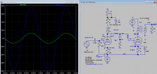
280V for the second stage 6SN7
Vg = -6V and Ia = 5mA
Voltage across 20kohm = 5 x 20 = 100V
Cathode resister is 1.2K
Cathode bias = 5 x 1.2 = 6V
Voltage across 6SN7 = 280 - 100 - 6 = 274V
I may like to raise cathode bias a little bit
280V for the second stage 6SN7
Vg = -6V and Ia = 5mA
Voltage across 20kohm = 5 x 20 = 100V
Cathode resister is 1.2K
Cathode bias = 5 x 1.2 = 6V
Voltage across 6SN7 = 280 - 100 - 6 = 274V
I may like to raise cathode bias a little bit
I did enough calculating by now. I think it would be good that you show us how you calculated the changes you now propose.
Thank you for your reply.
It is a good idea.
It is a good idea.
I would recommend you add a choke load, that would make life a lot easier. Doing this increased headroom swing, reduce distortion and ease of bias adjustment without affecting everything else too much.
Voltage across 6SN7 = 280 - 100 - 6 = 174V
Thank you for your reply.
280V for the second stage 6SN7
Vg = -6V and Ia = 5mA
Voltage across 20kohm = 5 x 20 = 100V
Cathode resister is 1.2K
Cathode bias = 5 x 1.2 = 6V
Voltage across 6SN7 = 280 - 100 - 6 = 274V
I may like to raise cathode bias a little bit
Correction:
In the previous protection schematic D1 1N4007 should be a Zener of 100V or so and R6 1Meg instead of 100k to reduce shunt loss.
In the previous protection schematic D1 1N4007 should be a Zener of 100V or so and R6 1Meg instead of 100k to reduce shunt loss.
Yes, should add protection circuit too.
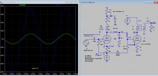
Please remove driver tube, and see the result.
Correction:
In the previous protection schematic D1 1N4007 should be a Zener of 100V or so and R6 1Meg instead of 100k to reduce shunt loss.
And the polarity of C3 should be reversed.
I have no experience with this kind of simulation/design software. Doesn't it warn against mistakes like this?
That is as good as if the bias supply is gone. So there is still multiple ground needs to be taken off. A fast blown fuse or crawl bar system or current limit maybe only way. A PTR can be used in conjunction with them if like.
But like you said cathode follower is safer, so an inductor can be use to increase headroom. The same problem if you lost -ve bias supply.
Yes C3 polarity is reversed, thank you.
But like you said cathode follower is safer, so an inductor can be use to increase headroom. The same problem if you lost -ve bias supply.
Yes C3 polarity is reversed, thank you.
Attachments

Last edited:
Thank you all for your replies.
There is a 100ohm VR between 300B cathode and the ground.
Equivalent R is 25ohm.
25ohm x 80mA = 2VDC if bypass cap exists.
About the protection circuit, my idea is to use an uC with ADC to monitor this voltage, shutdown HT relay when the voltage is over threshold to protect valuable 300B.
There is a 100ohm VR between 300B cathode and the ground.
Equivalent R is 25ohm.
25ohm x 80mA = 2VDC if bypass cap exists.
About the protection circuit, my idea is to use an uC with ADC to monitor this voltage, shutdown HT relay when the voltage is over threshold to protect valuable 300B.
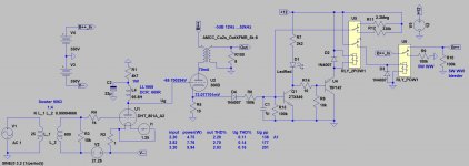
This is alternative to bias protection by grounding 300b cathode to -ve supply. The cathode resistor will limit the output tube current to a safe limit. There are many similar schematic on the net. -ve supply 280V can be further reduced to so stack voltage is with safety limit of OT.
Attachments
I agree it is a safe solution but it is quite a step away from the original idea.
From post #1: "I don't use high watt resistance to raise cathode voltage of 300B, instead I use negative voltage supply for second stage 6SN7."
The cathode resistor of 3K dissipates a little over 26 Watt. And when the bias fails it dissipates 38 Watt.
In this arrangement the 280 V supply must now also deliver current for 2 x 300B. So the current demand for the 280 V supply goes up from about 20 mA to about 250 mA (needed in case the bias in both channels fails).
Would a fast blow fuse in the B+ line to the OPT/300B not do the job?
At zero bias, if taken DCR (300) into account, total Pd=(347-51)*0.11=296)*0.11=32.6W.
So fuse is no required to blow as it's with same safe limit when it's biased Pd=(352-3.9)*0.092=32W.
PS this based on 300b model I have built, maybe different in actual amp.
So fuse is no required to blow as it's with same safe limit when it's biased Pd=(352-3.9)*0.092=32W.
PS this based on 300b model I have built, maybe different in actual amp.
Last edited:
I didn't mean adding a fuse to your arrangement. I mean adding a fuse in the original arrangement in which the 6SN7 and 300B don't have to share the 280 V supply.
Pd zero bias/bias Pd=110W/27W, current 420mA/80mA, it all depends on the current carrying ability of OT, some barely can do 100mA. So it appears a fast blown fuse 150mA can be used, not sure if every replacement fuse is consistent, that is the problem. I would prefer PTC the current can be more precisely specify and it has better tolerance. Due to high current expected it's wise to use these device injunction with other protections against arc, aging etc.
- Home
- Amplifiers
- Tubes / Valves
- 6SN7 > 6SN7 > 300B , 6SN7 DC 300B