I was intrigued by the DIY Sound Group Vortex 15 and the promise of olde time coaxial magic, but the recommended 6 cubic foot ported cabinet was impossible for my space. The 12" would probably be a better size for me, but when the 15" kits went on clearance last month, I decided to give it a go in a much smaller, sealed cabinet. According to Eminence and the designer, 2.5 cubic feet sealed gets you 75hz - 20khz. And I like sealed more anyway, so....
What should the sealed cabinet look like? I'm not concerned with the loss of bass because at 75hz I can add a sub later. Playing around with various calculators and the specs below, I also got 2.5 cubic feet. So I started there. The crossover was designed for a baffle 17" wide with the driver 3.25" from the top, so I kept those dimensions so that I can use stock crossover, although I'd love to try the 6-24 active crossover later. I wanted to keep the height at or below 37" to fit my space, and the depth in the 10-15" range for the same reason.
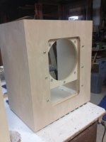
I taught myself some Sketchup and drew cabinets I think would work. Both use 18mm birch plywood, a double baffle and bracing to meet the designer's suggestions. The bracing in my drawings is for example only, with actual bracing designed later. One cabinet is a straightforward rectangle 17" wide by 32" tall by 12" inches deep; the second has an 8 degree sloped front like the Altec 618 cabinets, but bigger and braced. Both are nominally over 2.5 cubic feet.
The driver specs for the Denovo Hyperlite CX15-8 coaxial:
8 Ohm
98db - 2.83v/1m
Fs: 39.3hz
QM: 12.12
Vas: 259.2 liters
Cms: .249 mm/N
Mms: 66.1 g
SD: 856.3 cm^2
VD: 348.0
QE: .33
Re: 5.05 ohms
Le: 0.60 mH
Bl: 15.68 Tm
QT: .33
SPL: 98.6 1w/1m
Mmd: 51.7 grams
Xmax = 6mm,
Pe = 250w
Overall depth at 8.25"
How did I do? Suggestions?
Thanks!
What should the sealed cabinet look like? I'm not concerned with the loss of bass because at 75hz I can add a sub later. Playing around with various calculators and the specs below, I also got 2.5 cubic feet. So I started there. The crossover was designed for a baffle 17" wide with the driver 3.25" from the top, so I kept those dimensions so that I can use stock crossover, although I'd love to try the 6-24 active crossover later. I wanted to keep the height at or below 37" to fit my space, and the depth in the 10-15" range for the same reason.
I taught myself some Sketchup and drew cabinets I think would work. Both use 18mm birch plywood, a double baffle and bracing to meet the designer's suggestions. The bracing in my drawings is for example only, with actual bracing designed later. One cabinet is a straightforward rectangle 17" wide by 32" tall by 12" inches deep; the second has an 8 degree sloped front like the Altec 618 cabinets, but bigger and braced. Both are nominally over 2.5 cubic feet.
The driver specs for the Denovo Hyperlite CX15-8 coaxial:
8 Ohm
98db - 2.83v/1m
Fs: 39.3hz
QM: 12.12
Vas: 259.2 liters
Cms: .249 mm/N
Mms: 66.1 g
SD: 856.3 cm^2
VD: 348.0
QE: .33
Re: 5.05 ohms
Le: 0.60 mH
Bl: 15.68 Tm
QT: .33
SPL: 98.6 1w/1m
Mmd: 51.7 grams
Xmax = 6mm,
Pe = 250w
Overall depth at 8.25"
How did I do? Suggestions?
Thanks!
Attachments
Last edited:
I’d love it even more if I could make it a MLTL.
The complete opposite approach. Love it! Should be fun for both of us.
What should the sealed cabinet look like?
The driver specs for the Denovo Hyperlite CX15-8 coaxial:
8 Ohm
98db - 2.83v/1m
Fs: 39.3hz
QM: 12.12
Vas: 259.2 liters
Cms: .249 mm/N
Mms: 66.1 g
SD: 856.3 cm^2
VD: 348.0
QE: .33
Re: 5.05 ohms
Le: 0.60 mH
Bl: 15.68 Tm
QT: .33
SPL: 98.6 1w/1m
Mmd: 51.7 grams
Xmax = 6mm,
Pe = 250w
Overall depth at 8.25"
Well, since you've kept the width, driver offset of the original, the rest is just what you've done. 😉
WRT to the [preferred] sloped baffle, I presume you set the angle to put the tweeter at whatever ear height, so till bracing is designed........... 😉
I’d love it even more if I could make it a MLTL.
Presume you want the tweeter at what ear height?
Any dimension limitations?
WRT to the [preferred] sloped baffle, I presume you set the angle to put the tweeter at whatever ear height, so till bracing is designed........... 😉
Thanks for looking it over! I set the slope based on the Altec 618 cabinet, but the 8 degree slope, height and driver offset will work pretty well for ear height. For the rectangular cabinet I would probably need to build a stand that tilts the cabinet back.
I don't know why I would choose one bracing scheme over another provided there is enough. I've drawn the number and spacing for braces I think would work based on Morgan Jones' Arpeggio article, but round versus square or even open cutouts in the braces seem equivalent? When you say "till bracing is designed" am I missing something?
Grateful for the input.
Presume you want the tweeter at what ear height?
Any dimension limitations?
My ears are about 40” above the floor at listening position so circa 40” is a good target. With some toe-in, I can just about squeeze in a 25” total width after the beveled edges.
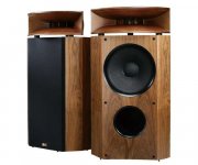
My initial inspiration was the Altec 605A in the 612 utility cabinets (see attached) but I want to do more for edge diffraction and LF than a straight clone of the 612 cabinet would afford.
Attachments

Last edited:
Thanks for looking it over!
I don't know why I would choose one bracing scheme over another provided there is enough..... When you say "till bracing is designed" am I missing something?
You're welcome!
I responded based on this quote:
The bracing in my drawings is for example only, with actual bracing designed later.
If the original has been proven to be sufficiently rigid enough to push the cab's Fs at least an octave above tuning where there's nothing to excite it, then good to go by most folk's performance goals, though with bracing dividing some relatively large areas in two, recommend adding some diagonal boards [nominal 1x3 min] placed/glued on edge [no fasteners] to break them up into random area triangles.
These shouldn't span the entire area as any hard joint creates a 'hot spot' [and why among other things I don't recommend the way it's currently braced from an engineering POV]; for example, the diagonal span is 20", so cut it ~0.707x = ~14.14" long and install offset from each corner, though can also offset at a different angle.
Thanks again!
I don't see a lot of examples of diagonal bracing in speakers, but I realize expedience drives a lot of design in commercial products. In structural engineering diagonal bracing is everywhere.
I don't see a lot of examples of diagonal bracing in speakers, but I realize expedience drives a lot of design in commercial products. In structural engineering diagonal bracing is everywhere.
Also see this thread. I measured both my drivers (they matched each other very closely) and then averaged the two’s measurements to come up with this:
Don’t know how big a difference it makes IRL vs the posted T/S at DIYSG.
Qts: 0.32
Vas: 206 l
Fs: 37.7 Hz
Re: 5.28 ohm
Le: 1.39 mH
Xmax: 6.0 mm
Qms: 10.12
Qes: 0.33
Bl: 15.68
Sd: 856.3 cm3
Don’t know how big a difference it makes IRL vs the posted T/S at DIYSG.
Don’t know how big a difference it makes IRL vs the posted T/S at DIYSG.
Cool, thanks!
Your measurements would suggest a smaller, sealed box of about 2 cubic feet, but not a whole lot of difference at 2.5. Good to know I could go a little smaller, though! I had considered that anyway assuming with stuffing I'd get back to approximating 2.5.
Don’t know how big a difference it makes IRL vs the posted T/S at DIYSG.
Thanks!
Per HR: huge difference in HF response from ~ 200 Hz - up in IB due to a much higher Le, otherwise a ~ 1.0 dB loss in efficiency all the way down.
Hopefully the XO won't need tweaking.
My ears are about 40” above the floor at listening position so circa 40” is a good target.
OK, all dims i.d. and approximate for ~Vb = Vas, ~Fb = Fs with minimal damping on top, one side and back per Altec:
L = ~61.444"
W = 25"
D = 22.348"
Ldr = 21.444"
Ldv = 52.104"
Dv = 8"
Lv = 3.58"
Attachments

What does this mean? Is it a proposal for a MLTL that is 61.44" high, 25" wide and 22.348" deep? What are the other numbers for? Does this file open in a certain app? If so, which one?
thanks!
thanks!
OK, all dims i.d. and approximate for ~Vb = Vas, ~Fb = Fs with minimal damping on top, one side and back per Altec:
L = ~61.444"
W = 25"
D = 22.348"
Ldr = 21.444"
Ldv = 52.104"
Dv = 8"
Lv = 3.58"
The text file imports into hornresp.
I also did not follow how GM arrived at those dimensions. Those dimensions led to a box much larger than suggested by the hornresp model.
I also did not follow how GM arrived at those dimensions. Those dimensions led to a box much larger than suggested by the hornresp model.
Hmm, good question! Sorry for the confusion! All these storms have wreaked havoc on my available hobby time. 🙁
FWIW, I typically use my well proven [ML]TL design routines to calc several 'quickie' alignments to compare and apparently listed one, but attached another, so will get this corrected once I get my latest storm damage cleanup done now that it's finally dry enough to not sink into the yard. 🙁
FWIW, I typically use my well proven [ML]TL design routines to calc several 'quickie' alignments to compare and apparently listed one, but attached another, so will get this corrected once I get my latest storm damage cleanup done now that it's finally dry enough to not sink into the yard. 🙁
Sims for your driver
Hi Jamayfie,
I have attached a couple of sims for your driver, looks like a good match in a small sealed box with a Q = 0.707 / Box volume of 72 litres.
I would guess your internal bracing and the volume of air occupied by the driver will = approx 8 litres so build a 80 litre box and you should be close.
Hope this helps and all the best
Alex.
Attachments
different Q options
PS
Increasing the Q to 0.8 = 53 litres (before bracing and driver volume).
Decreasing Q to 0.6 = 112 litres.
Decreasing Q to 0.5 = 200 litres.
The smaller the box box volume = lower sensitivity / lower SPL for the same power input.
The larger the box box volume = higher sensitivity / higher SPL for the same input power.
- Home
- Loudspeakers
- Multi-Way
- DIY Sound Group Vortex 15 sealed cabinet. Am I close?