So back to the bridging issue.
How should I wire up the output of each LM1876 - A or B or are both wrong?
B... however you will need to feed one channel with the INVERSE of the input signal, or alter the PCB so that one of the channels of each LM1876 is inverting. It is probably easier and safer to do the former with an opamp configured as an inverting buffer.
I thought it was B, but I wanted to be sure.
Sorry, I totally forgot to answer the crossover question.
It's a DOD 834 Series II.
With the input impedance issue and the need to invert one half of the output, this is far more complex a task than I suspected.
Sorry, I totally forgot to answer the crossover question.
It's a DOD 834 Series II.
With the input impedance issue and the need to invert one half of the output, this is far more complex a task than I suspected.
Things just got a lot easier!It's a DOD 834 Series II.
With the input impedance issue and the need to invert one half of the output, this is far more complex a task than I suspected.
The DOD has balanced, or at least differential, outputs. You don't not need to modify the amplifier, just drive channel A with the (+) output and channel B with the (-) output from the crossover for each output; then connect each speaker (+) to the channel A plus and the speaker (-) to the channel B (+). Repeat six times.
The input impedance of the amplifier is no longer an issue because you are not going to modify the amplifier chip input circuits for bridge mode, and you don't have to make any circuit modifications other than rewire the channel inputs. Problem solved!
(As it happens, the DOD being a professional audio product will drive 1kΩ inputs with no problems, but you don't need it if you take the approach above.)
Last edited:
Oh John, you've just made my day, cheers.
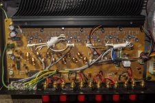
I've rewired the channel inputs by connecting the red and white wires together, the black wire I put to ground. The speaker outputs I've wired up as you say. I'll take some photos shortly.
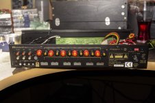
There are two more wires on each channel that aren't connected to anything and they are helpfully just labelled black and white, so I have no idea what they are for, I suspect they are to connect to the LEDs on the front of the chassis to show which channels are active, but I'm not sure.
There are some other wires that were connected to the input board that are now not connected to anything after I ditched that board, I haven't cut them off yet in case they might be needed, but as I have no service manual, I am working blind here, I don't see any use for them, but am not 100% sure yet.
I've rewired the channel inputs by connecting the red and white wires together, the black wire I put to ground. The speaker outputs I've wired up as you say. I'll take some photos shortly.
There are two more wires on each channel that aren't connected to anything and they are helpfully just labelled black and white, so I have no idea what they are for, I suspect they are to connect to the LEDs on the front of the chassis to show which channels are active, but I'm not sure.
There are some other wires that were connected to the input board that are now not connected to anything after I ditched that board, I haven't cut them off yet in case they might be needed, but as I have no service manual, I am working blind here, I don't see any use for them, but am not 100% sure yet.
Last edited:
Well, I tried it, but it doesn't produce any sound at all.
I'm guessing there is a purpose to the black and white wires connected to each channel, but without a service manual, I really don't know.
I'm guessing there is a purpose to the black and white wires connected to each channel, but without a service manual, I really don't know.
Something can't be connected correctly. If you drive one amplifier with the (+) signal from the crossover output and another with the (-) signal from the crossover output, and connect the speaker across the two amplifier (+) outputs, it will work - that's just a consequence of garden variety physics. Note: for it to work the DOD crossover must have differential outputs as per the owner's manual; i.e. (+) on tip and (-) on ring and ground on sleeve.
Last edited:
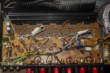
There is not much circuitry in there, I think you will be able to figure it out.without a service manual, I really don't know.
Start with the hints you were given.
The 10R got hot. Either its a very very bad design (too much power dissipation on the resistor) or there is a fault. The latter is likely.
Does it measure 10R?
If it is higher ohmage, chances are that the 7812 is defect and/or there is a problem after that.
Maybe it supplies the relays (do they click on turn on?). I´d guess not.
Measure the original 10R.
Measure the output from the (guess) 7812 that sits on the heatsink (you could measure at the connector (and mabye directly at the 7812 too).
Do the 12V go to the relais circuit, the transistors nearby?
Maybe the relais aren´t directly controlled from the 1237HA but the transistors which are eventually fed by the 12V.
Try to follow the tracks and see how its all connected.
These are just my guesses from looking at the pictures.
And don´t even think about bridging before it all works well.
Something can't be connected correctly. If you drive one amplifier with the (+) signal from the crossover output and another with the (-) signal from the crossover output, and connect the speaker across the two amplifier (+) outputs, it will work - that's just a consequence of garden variety physics. Note: for it to work the DOD crossover must have differential outputs as per the owner's manual; i.e. (+) on tip and (-) on ring and ground on sleeve.
Aah, that is probably the issue.
The cables I have have mono 6.35mm jacks on one end and RCA phonos on the other, the tip of the jack is wired to + and the ground is wired to the sleeve - there is no ring.
These cables worked fine with the unbridged stereo amps I had before.
I'll have to get some stereo jacks and make up some different cables.
- Home
- Amplifiers
- Solid State
- Bridge 6xLM1876 12 channel amp into 6 channels?