Hi folks
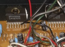
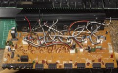
I've acquired a multi-room amp that uses six LM1876 chips to produce 12 channels.
I want to use it as a 6 channel amp so I'd like to bridge the output of each LM1876 into a single mono channel.
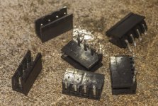
I've desoldered the speaker pin connectors with the aim of soldering on wires that I will then run to screw terminals I shall install in the back of the chassis, but I'm unsure as to how to connect those wires in order to bridge the outputs.
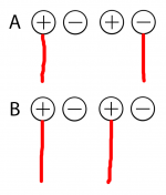
I'm also not clear on how to connect the inputs - each channel has the R and L inputs clearly marked, but I'm not sure how to connect them to a single input channel - connect R and L together so they are both receiving the same input signal?
I've acquired a multi-room amp that uses six LM1876 chips to produce 12 channels.
I want to use it as a 6 channel amp so I'd like to bridge the output of each LM1876 into a single mono channel.
I've desoldered the speaker pin connectors with the aim of soldering on wires that I will then run to screw terminals I shall install in the back of the chassis, but I'm unsure as to how to connect those wires in order to bridge the outputs.
I'm also not clear on how to connect the inputs - each channel has the R and L inputs clearly marked, but I'm not sure how to connect them to a single input channel - connect R and L together so they are both receiving the same input signal?
Attachments
-
 DSC00750.jpg273.3 KB · Views: 156
 -
 LM1876 Bridged.png55.7 KB · Views: 119
 -
 LM1876 Bridged 2.png182.2 KB · Views: 74
 -
 DSC00761c.jpg103.3 KB · Views: 68
 -
 DSC00761.jpg497.1 KB · Views: 66
 -
 DSC00760b.jpg459.3 KB · Views: 83
 -
 DSC00760.jpg511.1 KB · Views: 136
 -
 DSC00758.jpg430.1 KB · Views: 132
 -
 DSC00757b.jpg201.8 KB · Views: 167
 -
 DSC00757.jpg428.5 KB · Views: 142
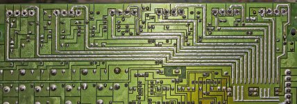
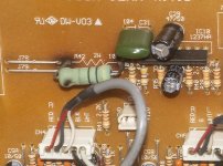
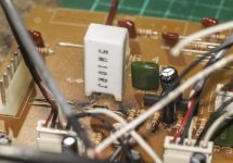
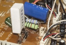
Also, I note there is an area where the PCB has got very hot and scorched, it is where a 2W resistor is placed. I note a black patch on that resistor which is concerning, so I think I better replace it with a 5W ceramic one.
The colour bands are gray, black, black and yellow, can anyone confirm that I am reading it right and it's an 80ohm resistor?
The colour bands are gray, black, black and yellow, can anyone confirm that I am reading it right and it's an 80ohm resistor?
Attachments
Unsure of the bridging, but that resistor looks to be a 10-ohm and a 3 watt should be the same size and be fine as a 50% updated part. Might be wrong but looks like a “10” on the board at that location - maybe??
Yeah, it says 10 on the board.
I think I already have some 10ohm ceramics in my box of parts, I'll have a look.
Thanks for your help.
I think I already have some 10ohm ceramics in my box of parts, I'll have a look.
Thanks for your help.
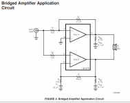
You can join inputs to bridge them as datasheet suggests but beware the bridged combination has vey low input impedance: 1K
Not an impossible load by any means but many preamps will not drive it, or with difficulty.
Also use 8 ohm speakers, not lower.
Not an impossible load by any means but many preamps will not drive it, or with difficulty.
Also use 8 ohm speakers, not lower.
What would happen if the preamp was unable to drive the 1k input?
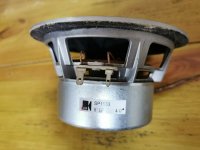
I'm not sure what the impedance of my speakers actually is as they are DIY ones I built myself.
I'm not sure what the impedance of my speakers actually is as they are DIY ones I built myself.
Almost no consumer audio components will be designed to drive into 1kΩ. The consequences might include attenuation of the signal level, limiting of bandwidth by rolling off both frequency extremes especially bass, and consequent phase shift, and increase in distortion of the source signal. You should ideally add a buffer stage to keep the input impedance above 20kΩ.
Also if you intend to use the extra available power you need ensure the heatsink is appropriate as the thermal dissipation in bridge mode is potentially higher. How many bass drivers in your speaker system? If there are two it will certainly fall well below 8Ω and the bridged amplifiers will potentially current limit and/or shut down with thermal overload.
Also if you intend to use the extra available power you need ensure the heatsink is appropriate as the thermal dissipation in bridge mode is potentially higher. How many bass drivers in your speaker system? If there are two it will certainly fall well below 8Ω and the bridged amplifiers will potentially current limit and/or shut down with thermal overload.
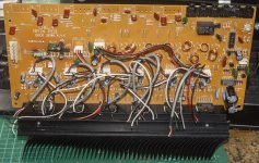
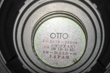
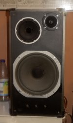
There's a 10 inch woofer, a 5 inch midrange and a 1" compression driver tweeter in each speaker, two speakers as it's a stereo pair. The 10" are 8ohms, the 5" are 4ohms, I don't know what the tweeters are, they aren't marked.
There's no crossovers in the speakers, I'm using a 3-way active crossover, hence the need for 6 channels of amplification, I was using three stereo power amps but two have bit the dust in the last week.
I have a couple of preamp options, one is based around a B1 buffer, maybe that would do the job?
There's no crossovers in the speakers, I'm using a 3-way active crossover, hence the need for 6 channels of amplification, I was using three stereo power amps but two have bit the dust in the last week.
I have a couple of preamp options, one is based around a B1 buffer, maybe that would do the job?
Attachments

With an active crossover you are unlikely to have current limiting on the midrange or tweeter because nearly all of the power is going to the bass driver (unless the high pass for the mid is very low).
However you might want to check whether amplifier noise is an issue in the mid or especially the high drivers. Noise may be worse in bridge mode, in which case it would be better to run those four or two channels not bridged.
Is the crossover an off the shelf unit? If so what brand and model? I might be able to give better advice if I know what you have.
Last edited:
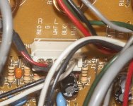
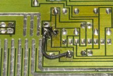
You can see that the tinned copper leads are conducting the heat from the resistor to the circuit board. When you replace the resistor mount the new one at least 6mm or preferably higher above the circuit board. This allows air to circulate around the resistor keeping it cooler and the longer leads mean less heat will get to the circuit board. I often wind the lead in a 'pigtail' loop, just to increase the heat sinking effect of the leads, whilst at the same time making the lead longer and further for the heat to go to get to the board.Also, I note there is an area where the PCB has got very hot and scorched, it is where a 2W resistor is placed. I note a black patch on that resistor which is concerning, so I think I better replace it with a 5W ceramic one.
It looks to me like some heat is also being generated by some or all of the six resistors mounted below IC10, as they are over the brown patch on the board. You could replace these with ½ watt rating and mount them above the board for air circulation. The values look like 10kΩ, 470Ω, 33kΩ, 2k2Ω, 33kΩ and 2k2Ω. The 470Ω resistor doesn't seem to be getting as hot as the others.
You can join inputs to bridge them as datasheet suggests but beware the bridged combination has vey low input impedance: 1K
There's another caveat with that particular bridging circuit. If you disconnect the input it will oscillate like crazy. That's because the chip has a minimum gain for stability and with nothing connected that gain gets to be 1 (well below the min recommended gain).
Running bridged into 8R the chip does get very hot when driven above a few W output power.
I always add extra copper beneath power resistors to act as a small heat sink.
I raise resistor a bit above pcb to get air beneath it too.
I raise resistor a bit above pcb to get air beneath it too.
Is the 10R ohm resistor (2W) connected to the 1237HA (speaker protection, relay controller)? Is this even working?
Maybe it connects positive supply and 1237HA for further filtering/delay.
Maybe it connects positive supply and 1237HA for further filtering/delay.
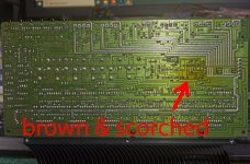
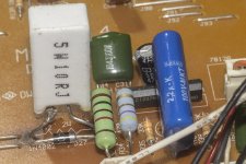
I replaced the 2W 10 ohm resistor with a 5W vertical ceramic one I happened to have, it;s mounted vertically with 4-5mm standoff from the board, hopefully this will work better heatwise, now the old resistor is gone you can see clearly how the board is brown and burned around the mounting holes. I retained the leads from the old resistor, I just clipped through them where they entered the resistor. I discovered that the heat had caused the track to lift from the PCB on one side, so I soldered on a piece of component lead to the underside as a repair for the lifting track.
Should I also replace the six resistors next door and the 2.2uF cap on the principle that heat is bad news for electrolytic caps?
Should I also replace the six resistors next door and the 2.2uF cap on the principle that heat is bad news for electrolytic caps?
Attachments
Give the discolouration under the 6 resistors they must be hot. Put your finger on them after the amp has been running for a while. It woudn't hurt to change that cap and the one on the other side of the IC as well.
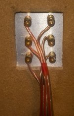
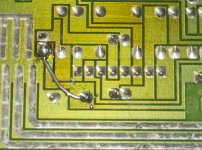
Where the wire is soldered to on the upper left, it doesn´t look like you have lots of clearance there (to GND or whatever that plane is).
The wire also crosses the plane in the middle which isn´t really good.
Solder resist is an insulator but still I´d be careful. Or use insulated wire.
I also see some residue of solder on the board.
The wire also crosses the plane in the middle which isn´t really good.
Solder resist is an insulator but still I´d be careful. Or use insulated wire.
I also see some residue of solder on the board.
Is the 10R ohm resistor (2W) connected to the 1237HA (speaker protection, relay controller)? Is this even working?
Maybe it connects positive supply and 1237HA for further filtering/delay.
I don't think there's a connection between them.
I'll replace the under board repair wire with an insulated piece.
Attachments
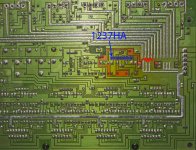
it seems the 10R/2W resistor is in line with the 7812 (it seems to go to that connector labeled 7812x), probably to keep the dissipation of the 7812 in check. And thus it will have considerable dissipation.
Check if 7812 and 1237HA work fine.
Check if 7812 and 1237HA work fine.
I'll find out if they work when I try the amp, is there a way of testing them otherwise? The connector has pins labelled +22v and -22V, so I don't think there is a 7812 reg on the power PCB, not sure, I'll have to check.
I only had 10k and 470R resistors and a 2.2uF cap, so I replaced those three parts. I will have to buy 47uF caps and 33k and 2k2 resistors if I am to replace those parts too.
I only had 10k and 470R resistors and a 2.2uF cap, so I replaced those three parts. I will have to buy 47uF caps and 33k and 2k2 resistors if I am to replace those parts too.
Attachments
Last edited:
- Home
- Amplifiers
- Solid State
- Bridge 6xLM1876 12 channel amp into 6 channels?